1ZSC000562-AAX en, Rev. 1 | Technical guide VUC 27
Highest phase service voltage across the regulating
winding
The table below show the highest permissible phase service
voltage for the different types of connections.
Across the regulating
winding (kV)
Across the coarse and
fine winding (kV)
Tap-changer,
tap selector
with
contact
shieldings
without
contact
shieldings
with
contact
shieldings
without
contact
shieldings
VUCG.N, B C - 35 - 40
VUCG.N, B III 52 35 75 45
VUCG.N, B F 52 - 90 -
VUCL.N, B III 52 35 75 45
VUCL.N, B F 52 - 90 -
VUCG.T, E C - 35 - 45
VUCG.T, E III 68 45 80 60
VUCG.T, E F 90 - 100 -
VUCL.T, E III
1)
68 45 80 60
VUCL.T, E F 90 - 90 -
Table 13. Highest permissible phase service voltage across the regulating
winding.
1) Higher values available on request. Please contact ABB.
Rated through-current
The rated through-current of the tap-changer is the current
that the tap-changer is capable of transferring from one
tapping to the other at the relevant rated step voltage,
and which can be carried continuously whilst meeting the
technical data in this document. The relation between rated
through-current and step voltage is shown in Figs. 36 - 37.
The rated through-current determines the dimensioning of the
transition resistors. The rated through-current is stated on the
rating plate, Fig.39.
Occasional overloading
If the rated through-current of the tap-changer is not less
than the highest value of tapping current of the tapped
winding of the transformer, the tap-changer will not restrict
the occasional overloading of the transformer, according to
IEC60076-7, 2005-12, and ANSI/IEEE C57.91-1995.
To meet these requirements, the VUC models have been
designed so that the contact temperature rise over the
surrounding oil does not exceed 20 K when loaded with a
current of 1.2 times the maximum rated through current of the
tap-changer.
The contact life stated on the rating plate is given with the
consideration that currents of maximum 1.5 times the rated
through current occur in a maximum of 3 % of the tap-change
operations. Overloading beyond these values, results in
increased contact wear and shorter contact life.
For more information about overloading, read the appropriate
parts of IEC 60214-2, 2004-10.
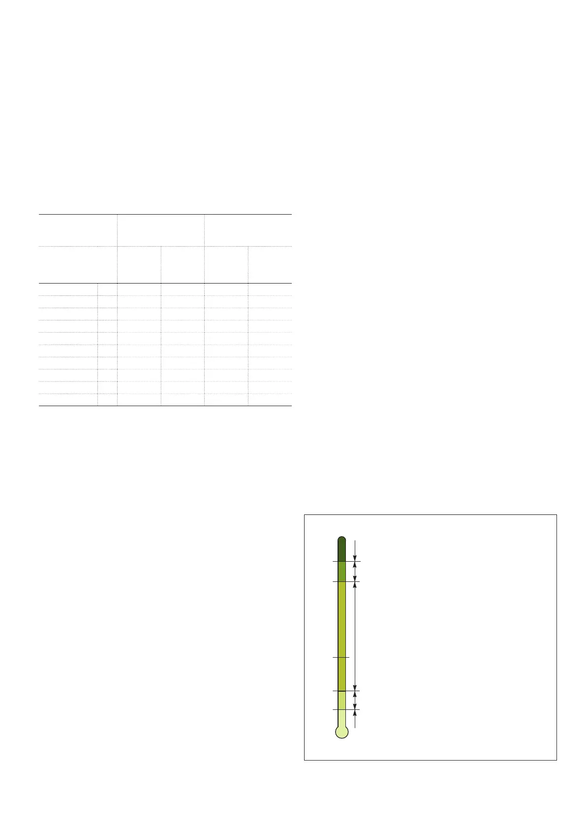
Oil temperature
Provided that insulating oil of class “Transformer oil -30 °C”
according to IEC 60296, 2012-02, is used, the temperature of
the oil surrounding the tap-changer shall be between -25 and
+105°C for normal operation, as illustrated in Fig. 43. VUCG
and VUCL can go to lower oil temperature than -25°C if low
viscosity oil is used; see Fig. 43, section 4.
For tap-changers in applications with >100 operations/day,
thermal monitoring is recommended. See product information
1ZSC000498-ACM.
Alternative insulating liquids
Individual brands need to be evaluated from case to
case because of the differences in viscosity compared to
transformer grade mineral oil and the subsequent difference in
heat dissipation. Also dielectric strengths and influence from
moisture need to be considered. Please contact ABB for more
information.
1. No operations allowed.
2. Emergency overloading. The tap-changer will
not restrict the occasional overloading of the
transformer according to the standards stated in
section Occasional overloading.
3. Normal operating range.
4. Operation possible under certain conditions.
Please contact ABB for advice.
5. No operation allowed.
Fig. 43. Oil temperature.
°C
-25
-40
0
+105
+115