1ZSC000562-AAX en, Rev. 1 | Technical guide VUC 19
Diverter switches
Type Max. rated through-current
VUCG.N, B
1
) 450, 600, 700, 800 A
VUCG.E, T
1
) 450, 600, 700, 800, 1600
2)
A
VUCL.. 700, 1000, 1300, 2600
2)
A
Table 1. Diverter switches.
1) Short version available in certain intervals, see Fig. 36. For dimensions, see Table 17.
2) Only available in E, T connection and requires forced current splitting during
operation, see that section. Contact ABB for more information.
Tap selectors
Type Connection Max. rated through-current Max impulse
test voltage
across range
C N, B 600 A 350 kV
1)
E, T 600, 1200, 1500 A 350 kV
1)
III N, B 1000 A 550 kV
1)
E, T 1000, 1800, 2400 A 550 kV
1)
F N, B 1800 A 550 kV
E, T 1800, 3600 A 550 kV
Table 2. Tap selectors.
1) Note that for certain positions, these values are lower. See Insulating levels.
Possible combinations of diverter switches and tap
selectors
Diverter switch VUCG VUCL
Tap selector C III F
Maximum number of positions
Type of switching Tap selector Max. number of positions
Linear C 18
III 22
F 18
Plus/minus C 35
III 35
F 35
Coarse/fine C 35
III 35
F 35
Table 3. Maximum number of positions.
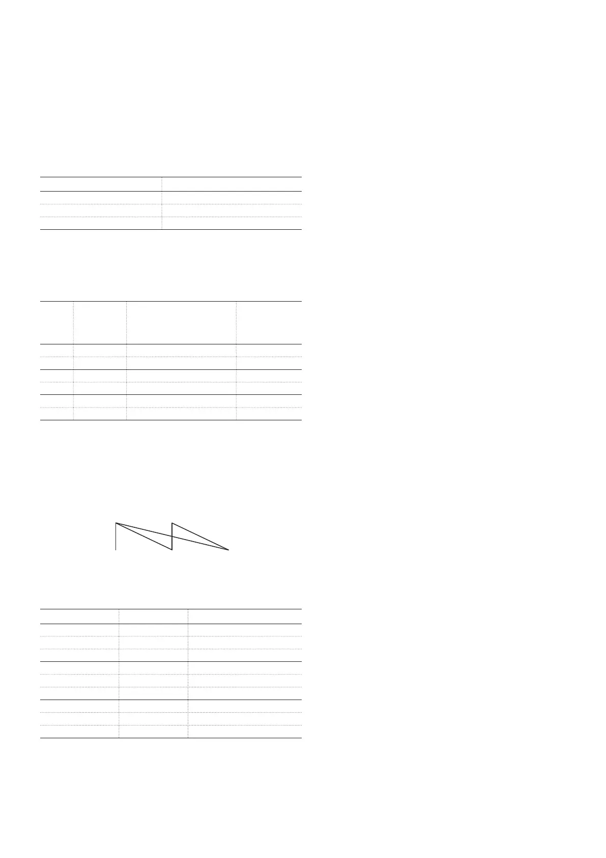
Enforced current splitting
In certain applications, two or more poles of a tap-changer,
or more than one tap-changer can work in parallel. However,
it is important to implement this in a correct way. There is a
difference between whether it should work in position (not
during operation) only or if it should work during operation.
During operation
Enforced current splitting during operation can be used when
the diverter switch has a lower current rating than the tap
selector or when two or more tap-changers work in parallel in
the same phase.
By having the same number of conductors in parallel through
the windings as there are poles or tap-changers in parallel,
parallel working conditions can be made to work. However,
the impedance between these parallel paths must be such
that the current through any of the poles or any of the tap-
changers must not exceed the rating of any of them. The
reason is that the poles in the diverter switch or the diverter
switches do not operate at exactly the same time.
To achieve this impedance, it is normally required that the
parallel conductors are kept separated through both the
regulating and the main winding. However, the impedance
between them must be calculated by the transformer
manufacturer in each case where enforced current splitting
during operation should be made use of.
See also IEC 60214-2, 2004-10, paragraph 6.2.9 for
information.