1ZSC000562-AAX en, Rev. 1 | Technical guide VUC 33
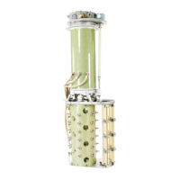
Dimensions
Dimensions, type VUCG
The design, technical data and dimensions are subject to
alteration without notice. The dimension drawings in this
guide show overall dimensions. For detailed information,
see the dimension drawings in the website www.abb.com/
electricalcomponents.
For tap
selector
size
Impulse withstand
voltage to earth
(kV)
H1
(mm)
H1,
short
version
(mm)
H3
2)
(mm)
H3
2)
,
short
version
(mm)
C 380, 650, 750 1192 972 1400 1200
1050 1492 1272 1700 1500
III 380, 650, 750 1354 1134 1400 1200
1050 1654 1434 1700 1500
F 380, 650, 750 1354 1134 1400 1200
1050 1654 1434 1700 1500
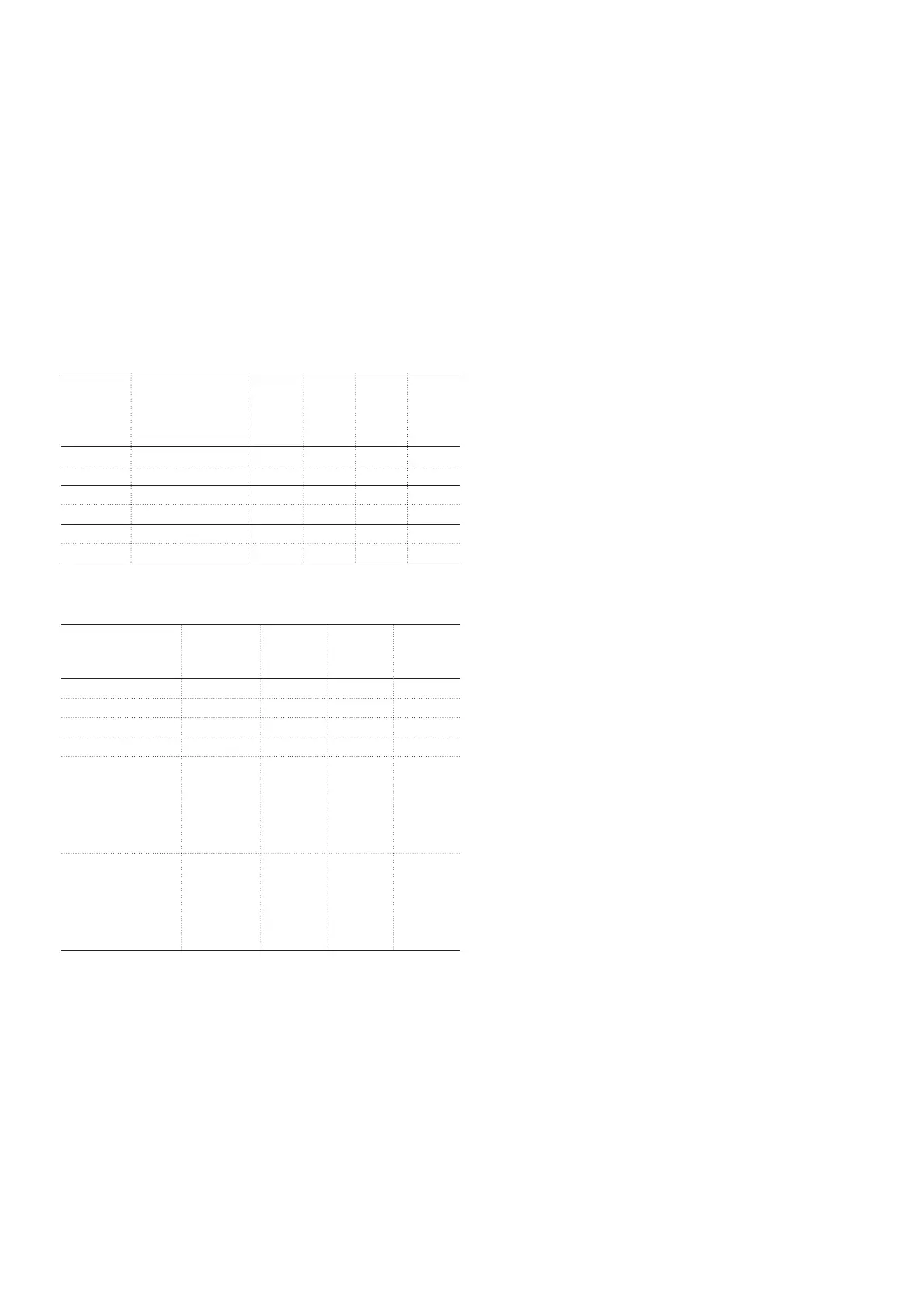
Table 19. Diverter switch housings.
For on-load tap-
changer type
Max rated
through-
current (A)
H2, size C
(mm)
H2, size III
(mm)
H2, size F
(mm)
VUCG.N 450-600 959 1160 1491
450-800 - 1160 1491
VUCG.E, VUCG.T
5)
450-600 519 552 791
601-800 739 552 791
VUCG.B
6)
450-600 Single
phase =
519
Two phase
= 739
Single
phase =
552
Two phase
= 856
Single
phase =
791
Two phase
= 1141
VUCG.B
6)
601-800 - Single
phase =
552
Two phase
= 856
Single
phase =
791
Two phase
= 1141
Table 20. Tap selectors.
1) Shielding rings are used only for insulation levels 650-275 kV and higher.
2) Space required for lifting the diverter switch, excluding the lifting equipment.
3) Dimension without shielding ring.
4) For tie-in resistor switch add 360 mm.
5) VUCG.T consists of three single-phase units.
6) VUCG.B consists of one single-phase and one two-phase unit arranged as shown in
the dimension drawing for UCL.B.
7) Space required for protective equipment.