1ZSC000562-AAX en, Rev. 1 | Technical guide VUC 29
HV
C1
RW
C2
+-
U
H1
The following limits apply to the change-over selectors of the
different tap selectors:
Tap selector Max recovery voltage
(kV rms)
Max capacitive current
(mA rms)
C 35 200
III 35 300
F 50 300
F 20 500
Table 14.
The capacitive current is the current going through the
change-over selector before it opens.
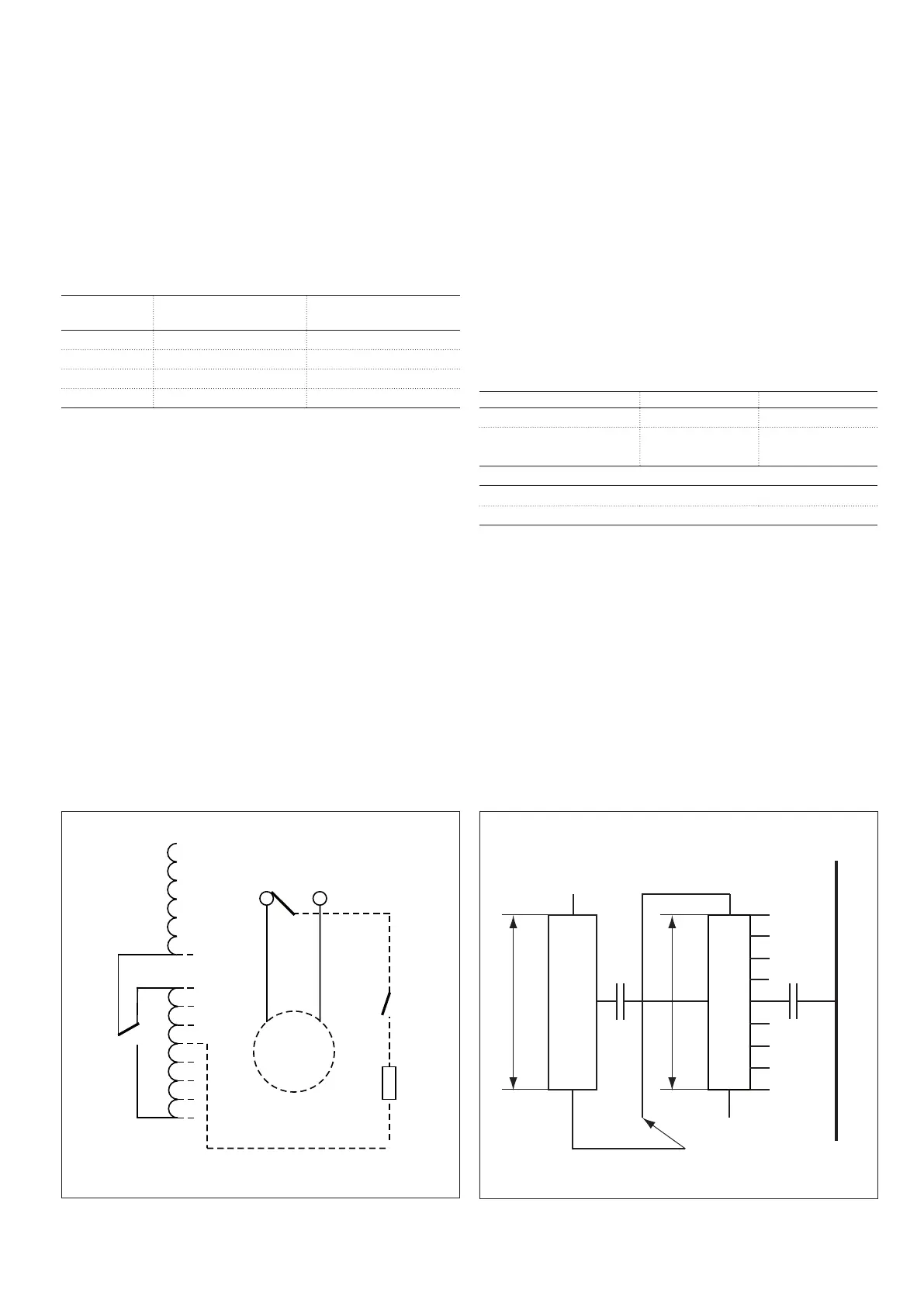
In Fig. 46 there is a switch, the tie-in resistor switch, which
connects the tie-in resistors only when they are needed. The
switch is a part of the tap selector and is mounted on the
bottom plate of the tap selector.
This switch is used when the no-load losses must be kept
low or/and when the continuous power in the tie-in resistors
is too high. The tie-in resistor switch is available only for tap
selectorIII and F .
Diverter switch
Tie-in
resistor
switch
Tie-in
resistor
Tap selector
Main
winding
Regulating
winding with
change-over
selector
Fig. 46. Tie-in resistor example. Fig. 47. Example of winding layout and information.
When ordering, give the winding layout and information
according to the example in Fig. 47 and Table 13, and ABB
will calculate whether tie-in resistors are needed or not. If
needed, ABB will choose the correct tie-in resistors. If a tie-in
resistor switch is needed to limit the no-load losses, give that
information in the ordering data sheet. If anything is unclear,
contact ABB.
Winding Phase voltage Connection
High voltage (HV) 132 kV (H1) Delta
Regulating winding (RW)
(Voltage across)
13.2 kV (U) Plus/Minus
C
1
= 3.8 nF (Capacitance between HV and RW)
C
2
= 2.0 nF (Capacitance between tank and RW)
Frequency 50 Hz.
Table 15. Example of winding layout and information.
Tank