30 | XSERIES G5 START UP GUIDE | 2106001MNAA
4 Wire COMM ports
Wire the XFC or XRC COMM ports to communicate with and power external
devices. Wiring for communication depends on the type of serial interface
required by the device. Wiring for power is required if there is no external
supply powering the external device.
Install the required communication modules in the correct slot on the XFC
or XRC board.
IMPORTANT NOTE: Refer to the XFC or XRC user drawings for COMM
generic wiring or detailed wiring for specific external devices. See
Additional information
.
Table 4-1: Serial communication specifications
Termination/connector type
(15 meters)
Screw terminal connector blocks,
removable for convenient wiring
NOTICE – Equipment damage. External devices can be powered
from the (VBAT) or (SW VBAT) pins on the XFC or XRC COMM ports.
The output voltage at these pins is dependent upon the external
power supply connected to the CHRG connector (J5 on XFC, J17 on
XRC). The voltage range at J5 or J17 can be from 9 Vdc to 15.5 Vdc
(The XFC and XRC are 12 Vdc nominal powered devices).
Before connecting an external device to VBAT or SW BAT, ensure
that the device is compatible with this voltage range.
incompatible device may result in damage to the device.
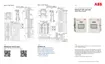
XFC COMM pinouts
To wire equipment to the XFC serial communication ports, determine the
COMM port to use, insert the correct communication module type in the
available slot, then refer to the generic wiring drawings or pinout tables.
IMPORTANT NOTE: Use pins on both terminal blocks to wire COMM1 or
COMM2 on the XFC. Remove both terminal block connectors from the
board to wire based on communication type
.
 Loading...