34 | XSERIES G5 START UP GUIDE | 2106001MNAA
If wiring for RS-485 communication, set the
termination jumpers (J11 or J12) in the correct position. See details in
Table
10-2 (COMM1) or Table 10-3 (COMM2).
XRC COMM pinouts
To wire equipment to the XRC serial communication ports, determine the
port, insert the correct communication module type in the available slot,
then refer to the generic wiring diagram or pinout table.
COMM 1 and COMM 2 have identical pinouts. Use J6-A to wire COMM1 or J6-
B to wire COMM2. See Figure 4-5 (RS 232) or Figure 4-6
(RS 485). Refer to
Table 4-3 for complete pinout for both ports.
When wiring for RS-485 communication, set the
ermination jumpers (J7 or J10) in the correct position. See details in
-2 (COMM1) or Table 10-3 (COMM2).
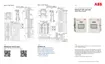
Figure 4-5: XRC RS-232 COMM 1
IMPORTANT NOTE:
Typically only TXD, RXD and GND may be required
to communicate with a third party RS-232 device. The figure above
illustrates all lines associated with COMM 1 or COMM2 RS-232 module.
Figure 4-6 (RS-485 COMM1) shows connection
lines to a single device. RS
-485 supports multiple devices per port.
For additional wiring options search a
dditional user drawings at
.
 Loading...