Capture/Sensing Thresholds. Capture and sensing thresholds should be determined with a PSA before
implanng the device. Connect the negave (black) PSA terminal to the poron of the lead terminal pin
corresponding to the p electrode. Connect the posive (red) terminal to the ring electrode poron of the
lead pin for bipolar leads or to an indierent electrode. For more informaon on conducng capture and
sensing threshold tests, please consult the PSA technical manual.
Establishing Baseline Capture/Sensing Thresholds. Aer the leads have been implanted and before they are
connected to the device, establish and document the baseline morphology for capture and sensing thresholds
for each lead using a suitable recording system, such as a 12‑lead electrocardiogram (ECG) or an intracardiac
electrogram (IEGM).
Implantaon
Physician Preparaon. The physician should be familiar with all components of the system and the material in
this manual before beginning the procedure.
Data Transmission. Implant the pulse generator no deeper than 5 cm to ensure reliable data transmission
with the Merlin
™ PCS or
Merlin
™
2
PCS
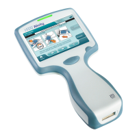
inducve telemetry wand. For MR Condional pulse generators,
implant the pulse generator no deeper than 4 cm to ensure reliable data transmission with the
SJM
MRI
Acvator
™ handheld device.
Paent Comfort. For paent comfort, do not implant the pulse generator within 1.25 cm of bone unless you
cannot avoid it.
Case Markings. Examine the markings on the device case and verify proper atrial and ventricular connecon.
Setscrew. Exercise cauon when turning the setscrew, which may be backed out of the connector if turned
counter‑clockwise for more than two rotaons.
23