PREPARATIONS, INSTALLATION AND TAKING INTO OPERATION
13
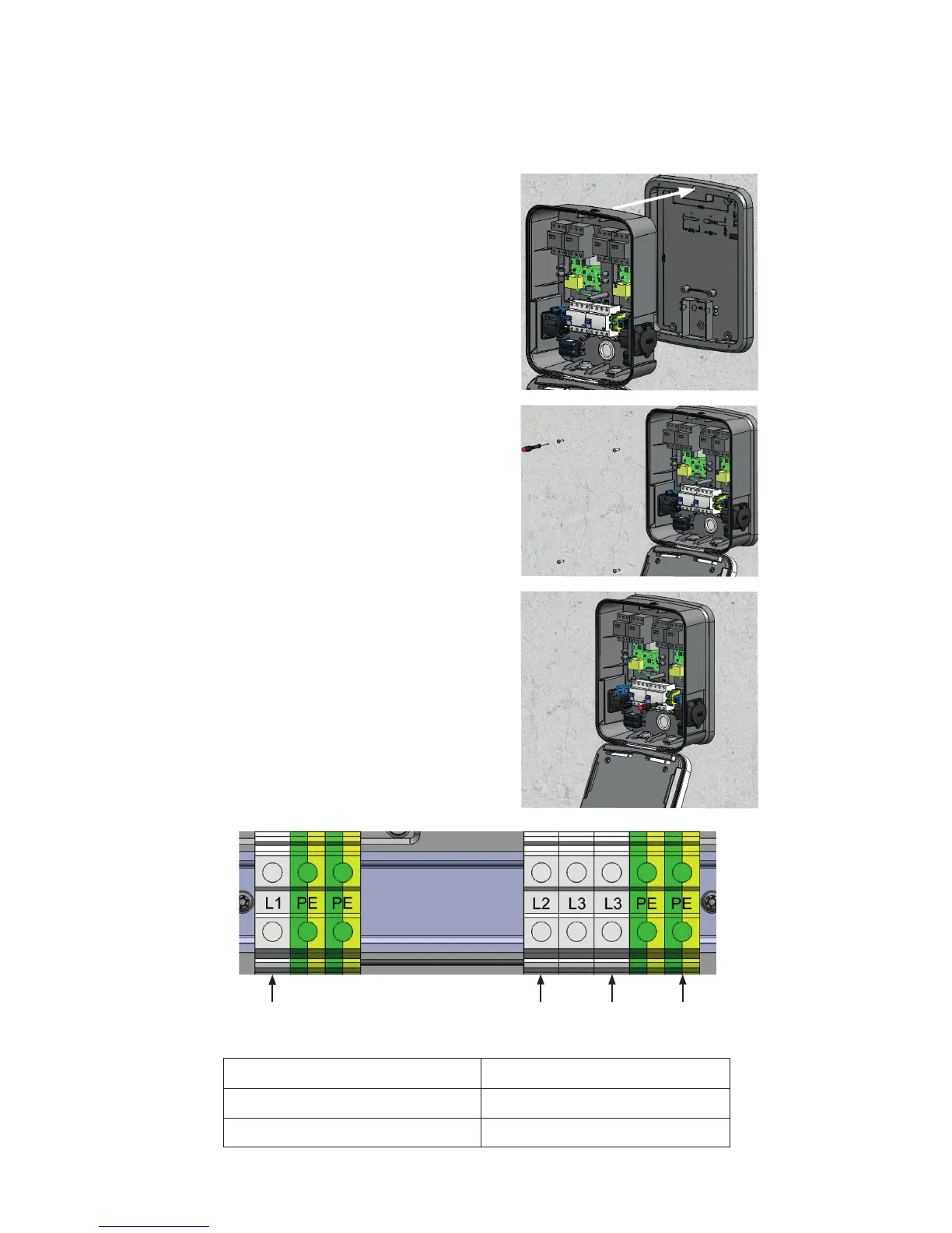
10. Hang the wallbox onto the mounting
plate by inserting the screw in the cen-
tre of the upper part at the rear into
the respective opening in the mount-
ing plate: this already protects the wall
box from falling.
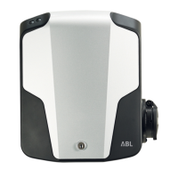
11. Now fix the wallbox to the mounting
plate using the screwdriver (TX25 bit)
and the four 6 x 25 screws included.
The wallbox is now securely fastened
to the mounting plate.
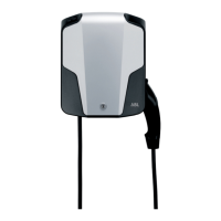
12. If using a power supply with flexible
wires, ensure that the stripped ends
are fitted with wire end ferrules. Loos-
en the lower screws in the terminal
blocks, insert the wires into their re-
spective terminal and tighten with a
torque of 2.5 to 3Nm. The wiring se-
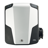
quence is shown in the following dia-
gram and table.
The supply cable for the model variants 3W14A1 and 3W14A2 is connected as follows:
DESIGNATION CONNECTION CODING
Current-carrying conductor L1/L2/L3
Protective earth PE
L1 L2 L3 PE



 To Next Page