LCFF 1.2 Setup & Calibraon
workshop manual v2
Page 11
© The Bicycle Academy Limited 2019
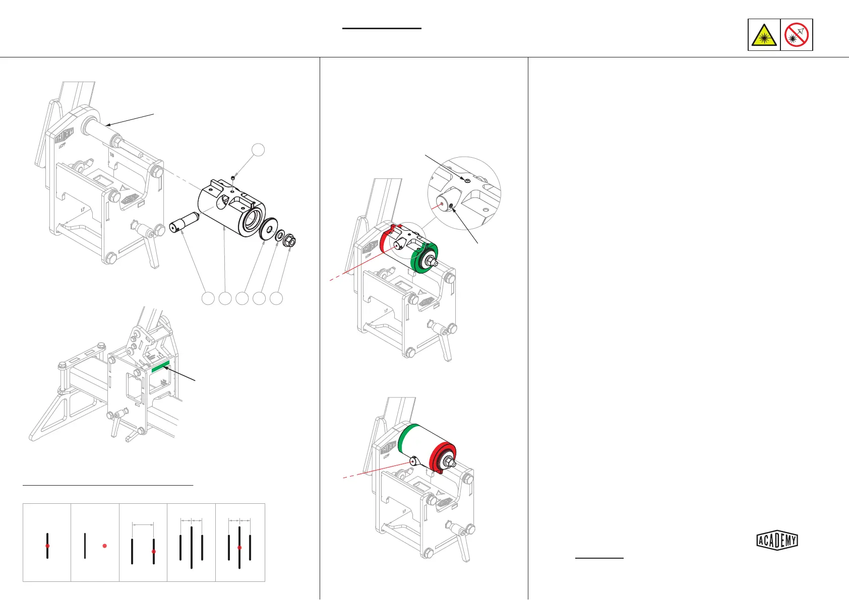
Laser Pointer Calibraon -
401 114 103 215 221
234
Detail A
Adjustment
grub screw
Set screw
A
Fig. 1
A
Fig. 2
A B
Fig. 3
A C B
Fig. 4
A C B
Fig. 5
Laser pointer calibra�on schema�cs
Direc�on and extent of ini�al error will vary
Masking tape
No BB spacer
Install the laser pointer into the BB laser holder
with one adjustment grub screw aligned horizontally as
shown in detail A and secure in place with the top set
screw.
Posion and secure the head tube carriage as far away
from the BB carriage as possible. Apply some masking tape
to the head tube carriage as shown.
(Fig. 1) - Turn the laser on and posion the laser holder
so that the laser dot strikes the masking tape. Clamp the
laser holder in place with the nut and mark a vercal line
through the centre of the dot (A). Turn the laser o.
(Fig. 2) - Without removing the laser from the holder, or
making any adjustment to the grub screws; re-orientate
the BB laser holder as shown. Switch the laser on and
adjust the rotaon of the holder so that the laser strikes
the masking tape at roughly the same elevaon as the rst
mark.
(Fig. 3) - Mark another vercal line where the laser strikes
the tape (B). It is important that the head tube carriage has
not moved since making the rst mark.
(Fig. 4) - Measure the distance between the marks and
make another vercal mark half way between (C).
(Fig. 5) - Adjust the horizontal grub screw on the pointer so
that the laser strikes the central mark.
Return the BB laser holder to its original orientaon and
repeat the process so that you are sased that the laser
strikes in the same place with the holder in both orienta-
ons.
This ESSENTIAL process veries that
the laser is projecng perpendicular
to the BB axis.
1.
2.
3.
4.
5.
6.
7.
8.
This ESSENTIAL process validates that the laser
is projecng perpendicular to the BB axis
Ensure the laser holder is securely
clamped with a consistent force each
me a measurement is taken.