LCFF 1.2 Setup & Calibraon
workshop manual v2
Page 16
© The Bicycle Academy Limited 2019
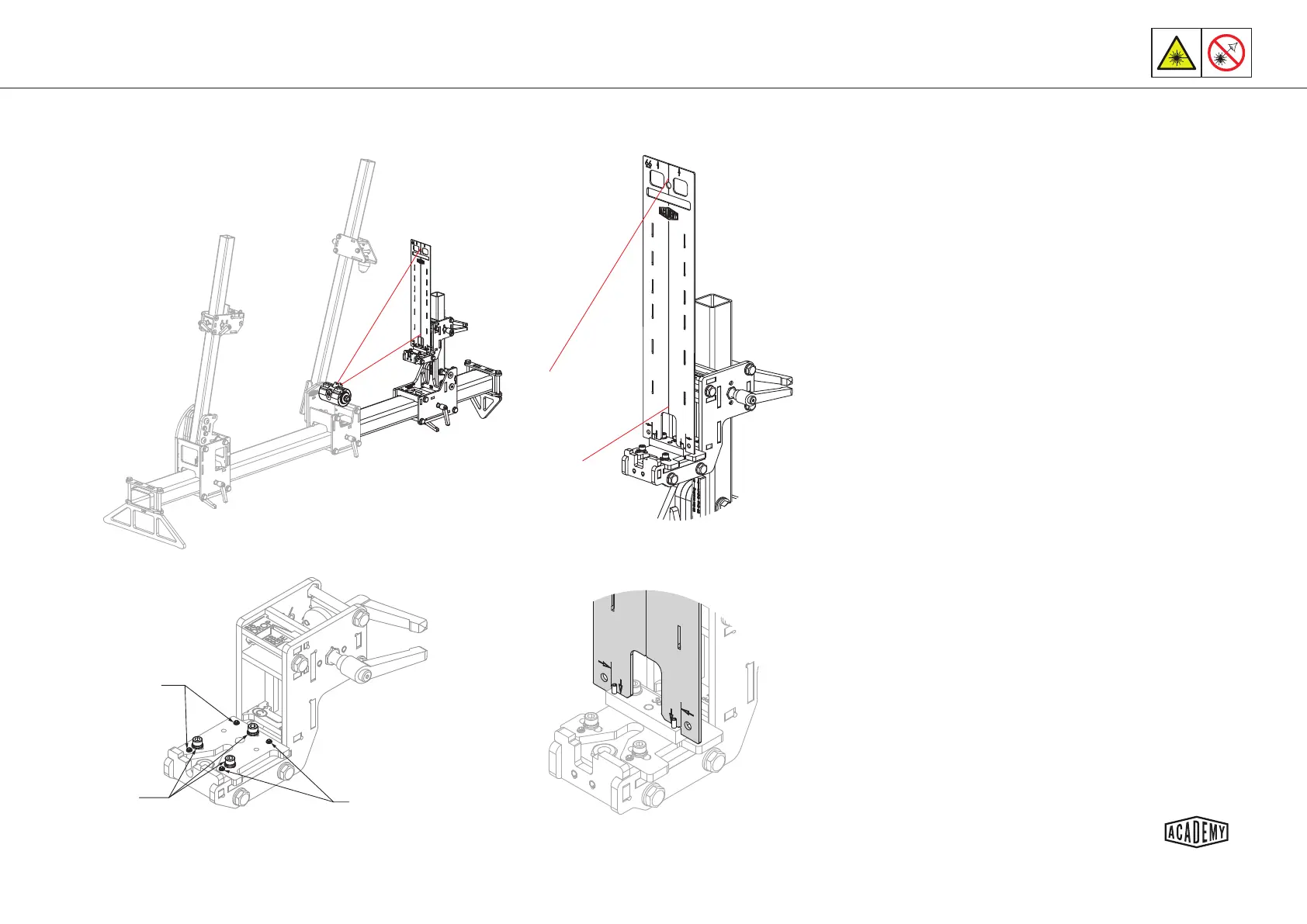
Adjustment
screws
Clamping
bolts
Adjustment
screws
Calibraon Step 3 - Rear Axle Centre Line & Roll
Set the xture rear axle X and BB drop/rise for the planned
frame build.
Insert the laser calibraon tool as shown and ensure it is
sing squarely on the dummy axle reference block.
Having calibrated the laser pointer (see page 11) aim the
laser at the lowest point on the calibraon tool and secure
the laser holder with a nut.
Slacken the 3x M5 clamping bolts to allow the rear axle slide
plate to slide and align the centre line of the calibraon tool
with the laser dot.
Aim the laser at the top of the calibraon tool and secure
the laser holder with the nut again.
Evenly adjust the grub screws on one side to align the cali-
braon tool centre line with the laser dot.
Take care to adjust both grub screws (see page 11).
Aim the laser at the base of the tool again, secure and slide
the rear axle slide plate if required. Tighten the 3x clamping
bolts evenly - DO NOT OVER TIGHTEN.
Repeat the process unl you are sased that the laser
strikes the calibraon tool centre line in both posions
shown with the 3x clamping bolts ghtened -
DO NOT OVER TIGHTEN.
1.
2.
3.
4.
5.
6.
7.
8.