VIRUS CLASSIC MANUAL 33
Introduction
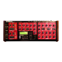
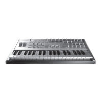
LFO 1
Start with the usual basic sound configuration or chose a modified sound to suit your taste. Locate
the RATE pot in the LFO 1 section of the control panel. The RATE pot is equipped with an LED that
indicates the speed of the LFO as well as its waveshape. Turn the RATE pot and check out how the
flash of the LED indicates the change of pace as you rotate the pot.
Currently you are unable to hear the effect of the LFO as its modulation intensity is set to 0 in the
sound program. In order to change this setting, you must access the AMOUNT button which works
in conjunction with five vertically arrayed LEDs labeled OSC 1, OSC 2, PW 1+2, RESO 1+2 and
ASSIGN: Press the AMOUNT button repeatedly and observe how the LEDs flash in succession (the
LEDs OSC 1 and OSC 2 flash separately as well as in unison). The corresponding modulation tar-
gets appear in the display, along with the modulation intensity values as determined by the VALUE
pot and VALUE buttons. (You can also scroll through the modulation targets via the PARAMETER
button after you have pressed the AMOUNT button once.) Once you have dialed in a value other
than 0 for a modulation target, the corresponding LED illuminates continually. This feature tells you
at a glance that a modulation is underway even when the display indicates some other type of oper-
ation.
Modulate the five parameters separately and in combinations with different intensities. Try to antici-
pate the sound you will come up with when you modulate the first oscillator, the second oscillator or
both oscillators at once and see if the results match your expectations. If you can fairly reliably pre-
dict the outcome of your sound-shaping efforts, you should have a handle on the information dis-
cussed thus far and can use your knowledge to create specific sounds you have in mind.
RESO 1+2
refers to the resonances of both filters. Please keep in mind that although
each set of these parameters is assigned a common modulation intensity,
you can still dial in different sound-shaping settings manually. In other
words, the audible result of a joint modulation varies according to the val-
ues you have determined for the other parameters.