-12-
Notes. ※1. Internal input resistance of volt-ohm meter should be higher than 10k-ohms.
テスターは、入力抵抗 10kΩ以上のものをお使い下さい。
※2. Adjustments should be made in case of the PC Board or Transistors being changed.
調整は PCボードあるいはトランジスタを交換した場合に行って下さい。
※3. Afer feeding 1~10watts output for about 15 minutes,check bias adjustments again.
出力1~10ワット前後で通電動作させた後、バイアス電流を再チェックする。
STEP
ステップ
ADJUST ITEM
調整項目
TEST EQ'PT
検出器
ADJUST
調整箇所
REMARKS
調整・備考
CONNECTING POINT
接続点
PROCEDURE
電圧検出
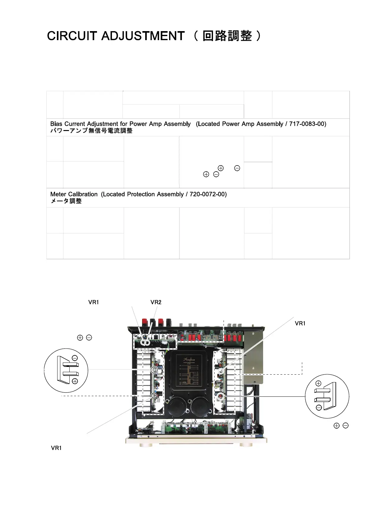
Bias Current of
L ch.Power Amp
Lch. バイアス電流ス
V.O. Meter set range
to less than DC 0.3V
テスター
DC 0.3V
以下のレンジ
Power Amp Assembly
パワーアンプ
Ass'y
(717-0083-00)
Test Point Pin and
テストポイント
,
VR1
for Lch.
Adjust for "
4
mV"
reading of V.O. meter
テスターの指示
"
4
mV"
に
調整する
Bias Current of
R ch.Power Amp
Rch. バイアス電流
VR1
for Rch.
1
2
Lch.
Power Amp Assembly
パワーアンプ Ass'y
(717-0083-00)
Bias Current
バイアス電流
Test Point
テストポイント
Rch.
Power Amp Assembly
パワーアンプ Ass'y
(717-0083-00)
Bias Current
バイアス電流
Protection Assembly
プロテクション Ass'y
(720-0072-00)
1
2
Peak-0dB Calibration
for Lch.
Lch.0dB
較正
Peak-0dB Calibration
for Rch.
Rch.0dB
較正
VTVM
Input:1kHz Sine Wave
入力
:1kHz
正弦波
Load :None
無負荷
Speaker Terminal
出力端子
VR1
VR2
Adjust input signal so that
VTVM reads
26.8
V.Then adjust
VR1 and VR2 so that Meter
reads 0dB.
VTVM
の指示が
26.8
V
になる入力
信号を入れ、メータの指示が
0dB
と
なるように
VR1,2
を調整
/
0dB for Rch.
/
0dB for Lch.
Test Point
テストポイント
 Loading...