2-2 System Components User Manual
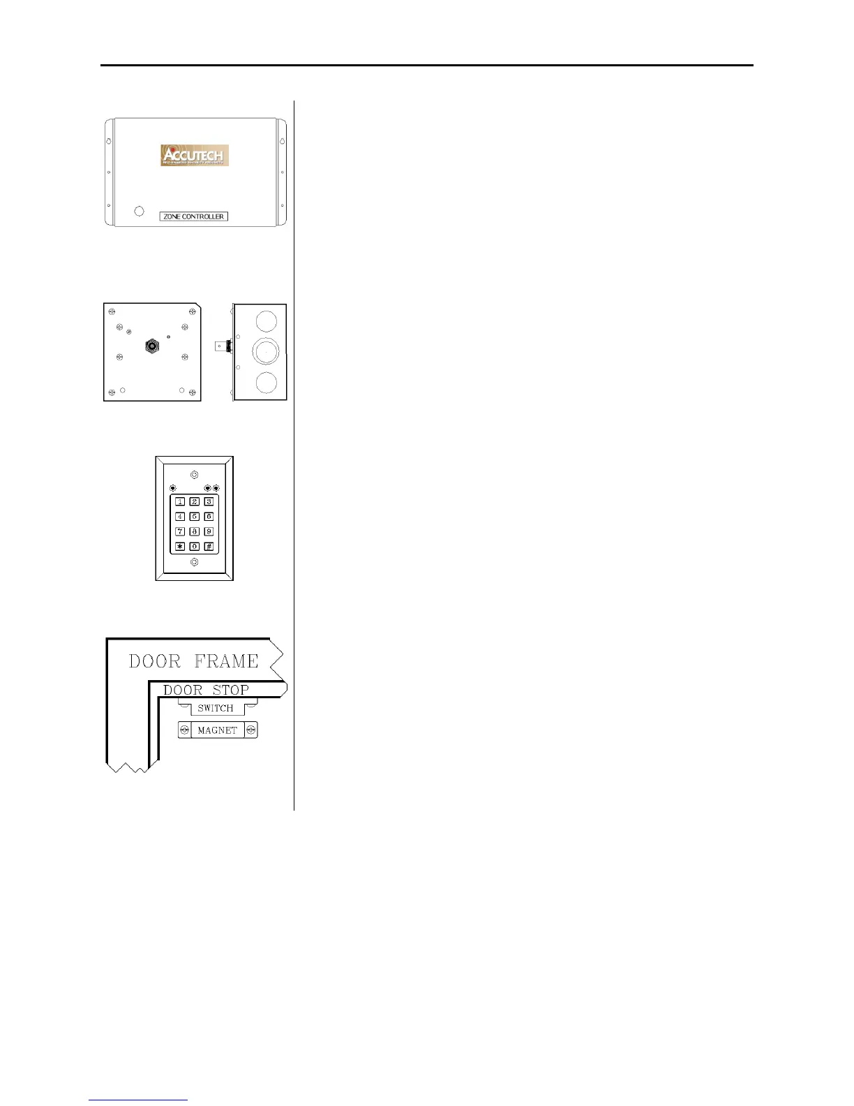
Figure 2.1 The Controller
Controller
The Controller (Figure 2.1) coordinates and controls all of the devices
and functions of the Accutech Security System.
Figure 2.2 Receiver
Receiver
The Receiver (Figure 2.2) picks up the signal from an activated Tag
and relays it to the Controller and the Multiplexer. Receivers can be
internally or remotely mounted near a monitored zone.
Figure 2.3 Keypad
Keypad
The Keypad (Figure 2.3) is used to escort residents or infants through a
monitored zone and to reset zone equipment once an alarm has
occurred.
Figure 2.4 Magnetic Switch
Magnetic Switch
The Magnetic Switch (Figure 2.4) is used on a door when alarm
activation is not desired unless the door is opened.