1-13Chapter 1: The LC1400 System
Red LED indicates active fire alarm event or no fire panel connection.
Green LED indicates no active fire alarm event and a fire panel connection.
Elevator Deactivation
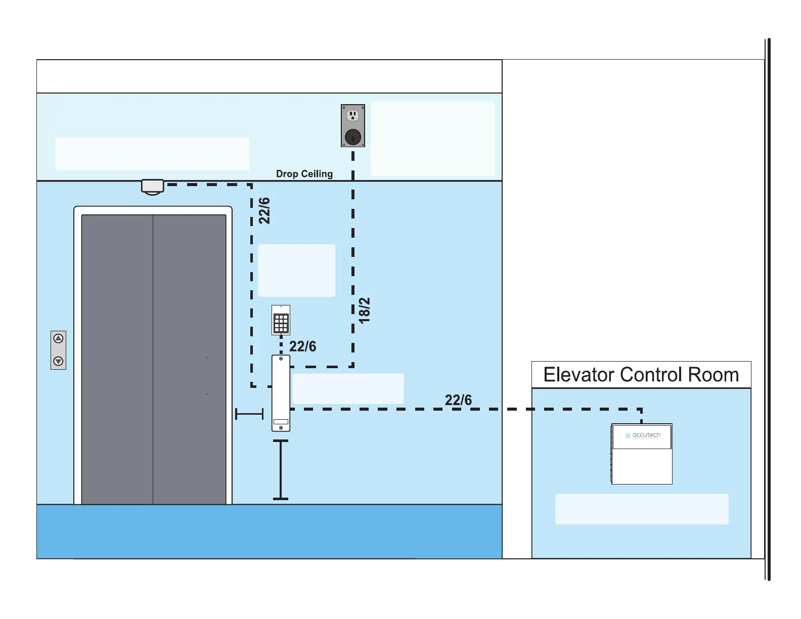
Typical LC1400 Configuration - Single Elevator
15VDC/2A
Plug-in Power
Supply
Part #500224
Passive Infrared Reader
Part #300302
KP103
Keypad
Part #650209
~2’
from
floor
Min
3”
from
frame
LC1400T
Part #662022
Elevator Deactivation
Part #700027
Important:
15VDC/2A Plug-in Power Supply
(Part #500224):
•Installed above drop ceiling
Passive Infrared Reader
(Part #300302)
• Position facing down toward floor
• Mounted at corner of wall and ceiling
LC1400T
(Part #800128):
•Not designed for ceilng mount.
•Position at least 3” away from any metal.
LC Hallway/Elevator Kit
(Part #800128):
•LC1400T (1)
•LCT-TX (1)
•Keypad (1)
•Passive Infrared Reader (1)
•Cable Kit (1)
•15VDC/2A Power Supply (1)
 Loading...