Chapter 2: The LC1400T2-12
J2 (RS485)
J2 RS485 Connection
See 7-2. Figure 7.1
Used to configure and change settings in the
LC1400T or LCT-TX only
B
A
G
JP1
J4
J2
UNREG
TX-ANT
GND
PWR
LF TUNING BOARD
1
5
LED1
LED2
C1
J1
SW1
C4
JP6
CH
RS485
TERMINATING
JUMPER
RESET
TUNING LED
ENABLE
DO NOT ADJUST C4
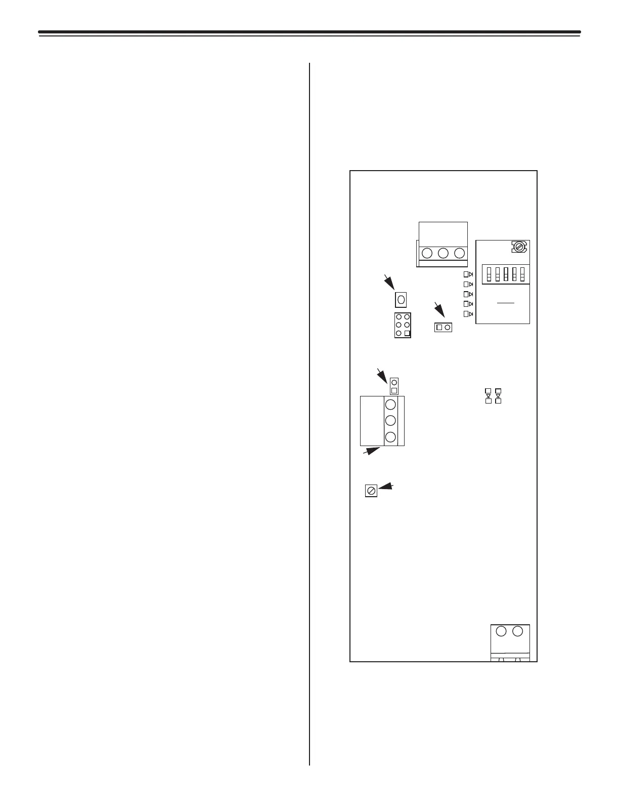
Fig. 2.13
LCT-TX Only
The Circuit Board
• LEDs
• LED Displays
• Jumpers
• Low Frequency Tuners
• Switches
• Power Input
• Terminals
LEDs
LED1 (Alarm/Error) (Red)
LED2 (Power Indicator) (Green, Solid)
LED Displays
LED-X
(Bar Display X-Axis) (Blue)
This Bar Display indicates that the X-axis is
powered and displays its relative Tx Output
level.
Jumpers
JP1
(RS485, Terminating Resistor)
Default position: In
In: Add resistor
Out: Remove resistor
JP6
Tuning LED Enable)
Default position: In
In: Tuning LED Enabled
Out: Tuning LED Disabled
Terminals
J1 (Power)
J1 - 1 (Power for board)
VN Regulated 15 VDC
J1 - 2 Ground for board
Switches
SWI (Micro Reset push button)
 Loading...