2-11Chapter 2: The LC1400T
Low Frequency Tuners (LFTs)
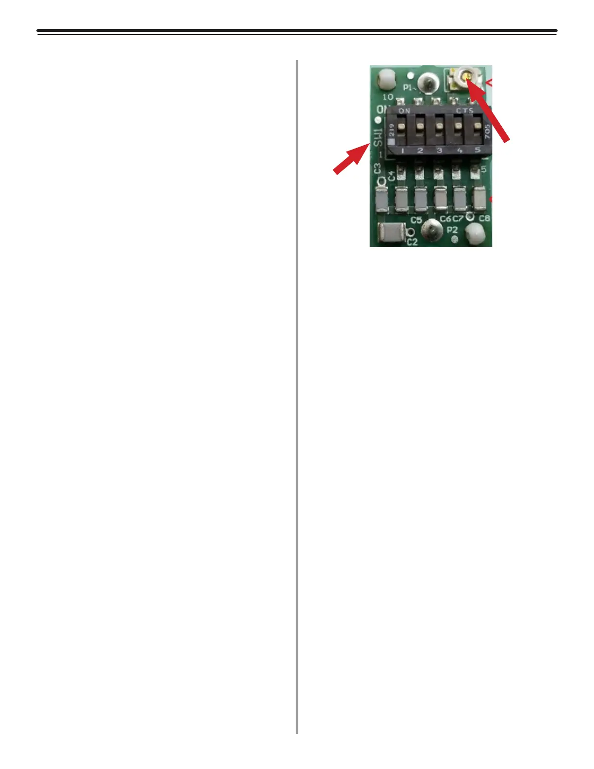
SW1 on LCT
Sets frequency of Tx Activation field
C1 (Fine variable tuning cap)
This tuning cap fine tunes the Tx Activation
Field strenth of the X, Y, and Z axis.
See figure 2.6 for location
See figure 2.7 for dip switch configurations
Switches
SW1 (Micro Reset Push Button)
Tamper Infrared Sensor
The tamper infrared sensor (IR1) is provided to
prevent unauthorized access to the LC1400T.
An alarm will be generated if the LC1400T
cover is removed. (Power to the unit is required
for the infrared sensor to function).
A small piece of foam with reflective tape is
glued inside of the controller cover to reflect
infrared light back to the sensor. Do not
remove this piece of foam or its reflective tape.
Potentiometers
R9 (Volume Control)
Default setting: Full scale
This potentiometer controls the volume of the
internal peizo.
Fine
Variable
Tuning
Cap
SW1
on
LFT
Figure 2.6
Low Frequency Tuner