SP8026-1909
EVOLUTION ELECTRIC STEAMER
36
4.3 Removal and Replacement of Heat Control Components
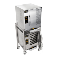
MAIN CONTROL BOARD
1. Unplug the Unit.
2. Remove the Left-Side Panel by removing the
Sheet Metal Screws holding it in place.
3. Disconnect the wires (note the wire color to
its location terminal).
4. Remove the 7 mounting nuts and then
remove the Control Panel CCA.
5. (If accessing the Program Mode is needed,
go to page 10 for more details.)
6. Re-install in reverse order.
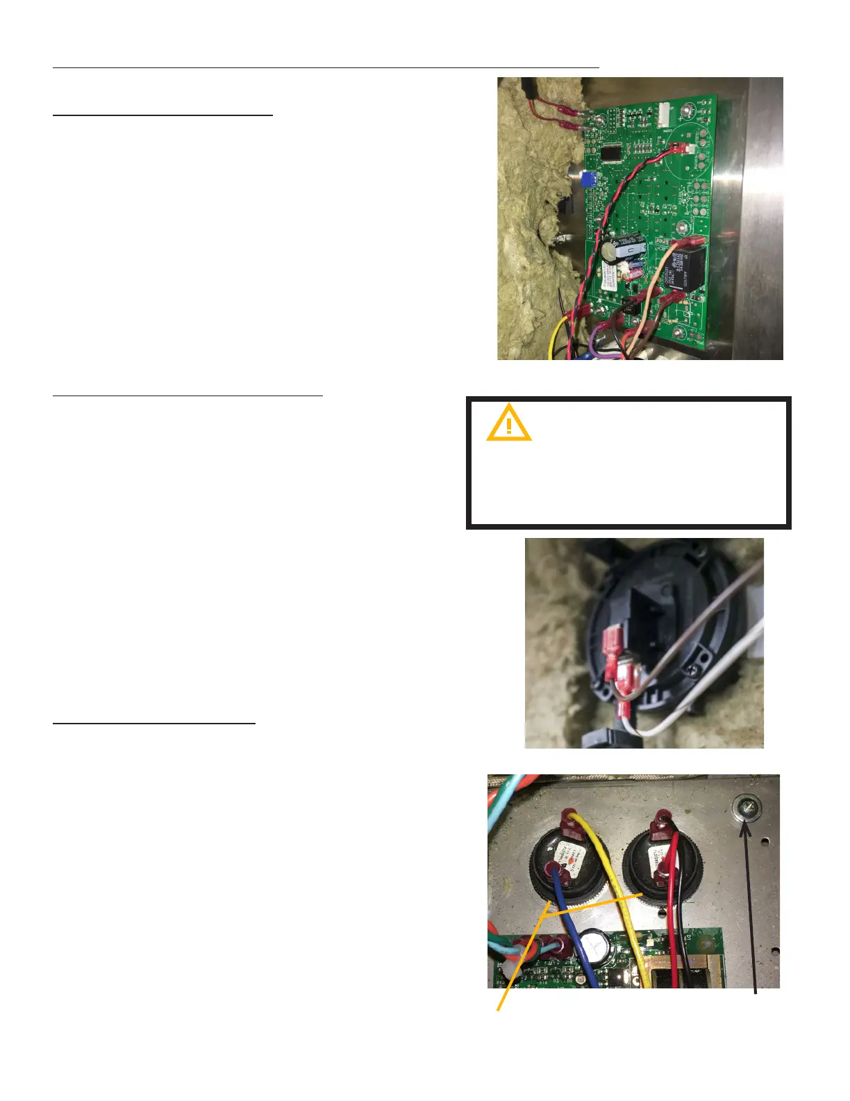
CHAMBER PRESSURE SWITCH
1. Unplug the Unit & remove the Left-Side
Panel by removing the Sheet Metal Screws
holding it in place.
2. Disconnect the Wiring Terminals from the
Chamber Pressure Switch (note the wire
color to its location terminal).
3. Remove the hose clamp and disconnect the
hose from the Chamber Pressure Switch.
4. Remove the 2 mounting nuts holding the
Chamber Pressure Switch to chamber cavity.
5. Remove the Chamber Pressure Switch
6. Re-install in reverse order.
FIG 4.3A
FIG 4.3B
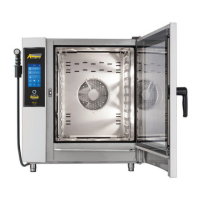
ALARM ENUNCIATORS
1. Unplug the Unit.
2. Remove the 4 Sheet Metal Screws at the
bottom of the Front Panel.
3. Disconnect wires to enunciator:
A. CONTROL BOARD - red and black
wires.
B. WATER SYSTEM - Blue and Yellow wires
4. Remove the phillips round-head
machine screw(s) from the component
bracket and lift bracket out.
5. Unscrew Enunciator from component
bracket
6. Reinstall in reverse order.
Do not remove board from the
anti static bag until ready to use.
A grounding strap is recommended to
remove static
FIG 4.3C
Round head
machine screw
Enunciators