3-36 Machine Maintenance Procedures
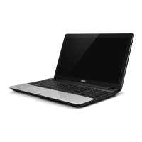
3. Remove the base assembly from the LCD module (Figure 3-34).
Figure 3-34. LCD Module
Make sure all cables are moved away from the device to avoid damage
during removal.
LCD Module Installation 0
1. Place the LCD Module on the Base Assembly. Refer to Figure 3-34.
2. Align LCD hinges (B) with the hinge guides on the Base Assembly. Refer to
Figure 3-33.
3. Install and secure four (4) screws (A). Refer to Figure 3-32.
4. Install mainboard.
ID Size Quantity Screw Type
A M2.5*6.5 4
 Loading...