1-12
• All wires must be firmly connected.
• Make sure all the wire not touching the refrigerant piping, compressor or any moving parts of the fan motor.
• The connecting wire between the indoor unit and the outdoor unit must be clamped on the wire clamps.
• The power supply cord must be equivalent to H07RN-F (245 IEC65, 245 IEC66) which is the minimum requirement.
• When attaching the terminal box lid, make sure do not pinch any wires.
• After all the wiring connections are done, fill in any gaps/holes with insulation (procured locally) to prevent small animals
and insects entering the unit from outside.
• Use round crimp-style terminal for connecting wires to the power supply terminal block. Connect the wires by matching to
the indication on terminal block. (Refer to the wiring diagram attached on the unit).
Model Indoor 5CE35ER (5)CE40ER
Outdoor 5SL35CR (5)SL40CR
Voltage range 380-415V/3Ph/50Hz +
!
Recommended fuse* (A) 10 13
Power supply cable size* (mm
2
) 1.5 2.5
Number of conductors 55
Interconnection cable size* (mm
2
) 1.5 1.5
Number of conductors 3&4 3&4
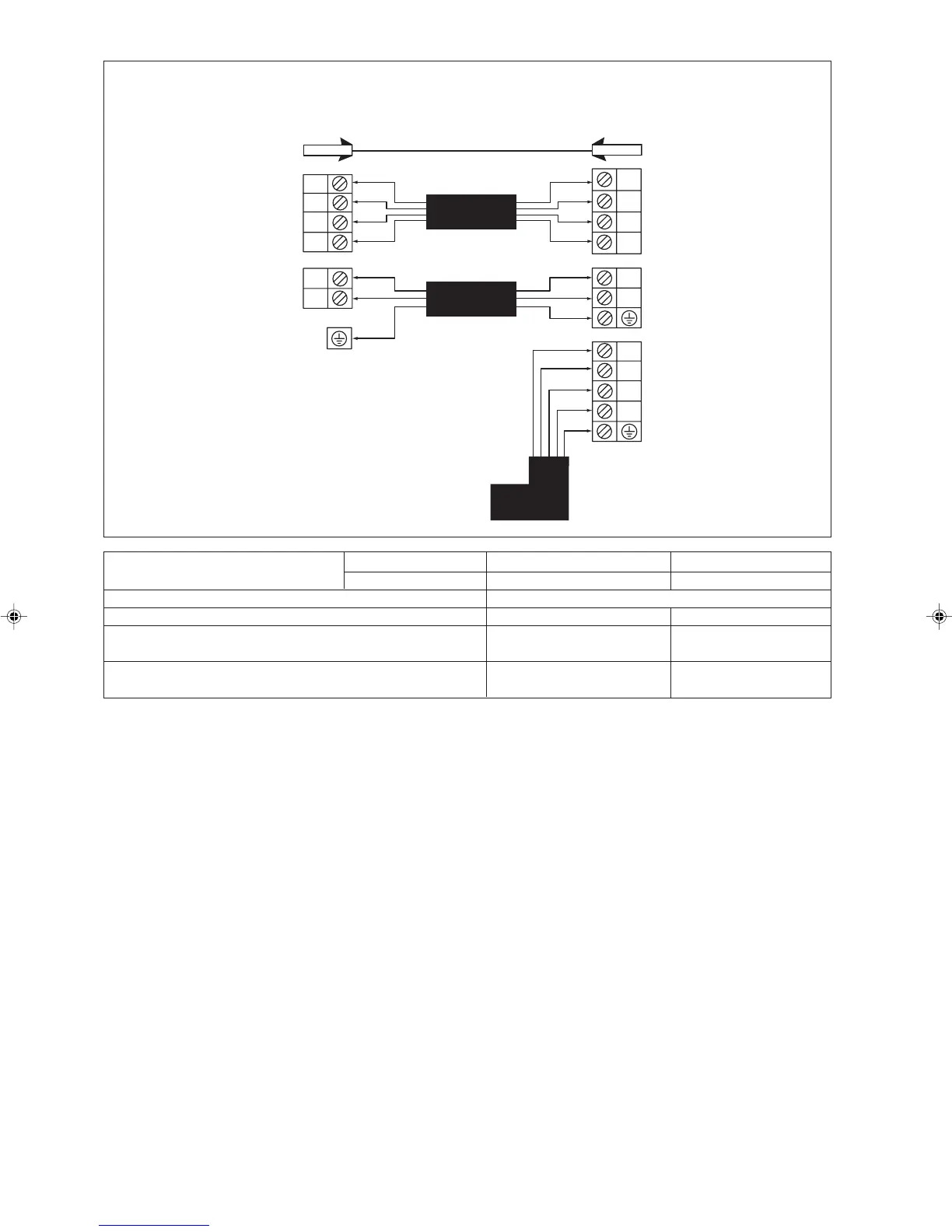
A
4WV
OF
COMP
A
R
S
T
4WV
OF
N
COMP
N
L
N
L
The electrical power must be provided with
protection devices (circuit breaker or fuse) with
double pole separation system (phase + neutral)
with minimum contact gap of 3.0mm.
(5)CE40ER Vs (5)SL40CR (3PH)
5CE35ER Vs 5SL35CR (3PH)
Indoor Unit
Terminal
Block
Interconnection
Cable
Outdoor Unit
Terminal
Block
!
Power Supply Cable
380-415V/3Ph/50Hz
Outdoor Coil Sensor
1 IM-CEE-1108(0)-EN AS 5/26/09, 3:14 PM12