Installation and Commissioning Guide
Split Ducted Units
PRELIMINARY DATA ONLY Ver. 3.03 220620
THIS LABEL TO BE REMOVED ON SIGN-OFF
16
Installation and Commissioning Guide - Split Ducted Indoor Unit
Doc. No.0525-084 Ver. 3 22xxxx
Airflow Application Guidelines
ActronAir Advance systems are designed with a self-learning function to sense the installation zoning of a system to
deliver the required balanced airflow. The following are some recommendations to make this system work to its optimum
design.
Duct Static Pressure
The ideal system design is for a duct with a Tl Static pressure of 125Pa. This design static for the VAF (variable air flow)
system allows for the optimal combination for duct sizing and energy efficiency of the system. This compares with 150 to
250 Pa for standard systems.
Final and Return Air Duct Sizes
There are set parameters for sizing and design of both final duct (from the last take off to the outlet) and return air duct
and fittings. The following duct sizes are based on a maximum final duct air velocity of 3 m/s and a maximum return air
velocity of 4 m/s.
Other Recommendations are:
• Main duct velocity is recommended to be within 6-7 m/s.
• Branch duct velocity is recommended to be within 4-6 m/s.
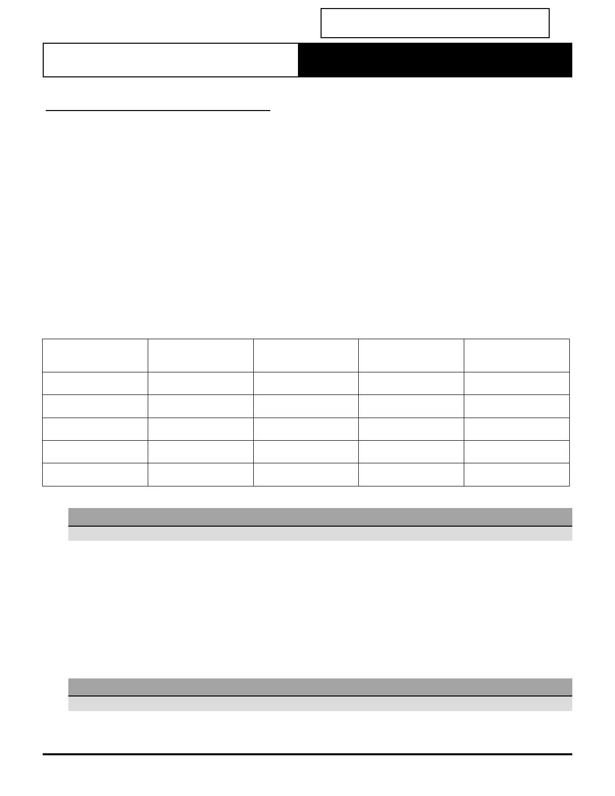
Model
Nominal Supply
Air Flow (L/s)
Minimum Supply
Air Flow (L/s)
Minimum Final
Air Duct Sizes
Return
Air Duct Sizes
EVV140S / EFV140S 630 220 1 x 300 or 2 x 200 2 x 350
EVV160S / EFV160S 750 250 1 x 300 or 2 x 200 2 x 400
EVV180S / EFV180S 850 300 1 x 300 or 2 x 200 2 x 400
EVV210S / EFV210S 1020 350 1 x 350 or 2 x 250 2 x 450
EVV240S / EFV240S 1130 400 2 x 250 2 x 450
NOTE
Above values are designed to minimize noise generation at supply air outlet.
To reduce noise issues at the supply air grilles careful consideration must be taken when designing for minimum air
quantity.(See above table) e.g. an EVV180S / EFV180S has a minimum supply air quantity of 300 l/s, this is too much airflow
for 1 x outlet to handle and in this instance 2 x outlets correctly sized is recommended.
• On minimum zone selection two outlets should be considered for airflow and noise purpose.
• Systems larger than 13kw it is recommended to have 2 x outlets or more for minimum zones.
When an air balance is carried out, it is recommended that the airflow is adjusted at the branch take off points to each
outlet is recommended instead of balancing dampers at the supply air outlet. This will also reduce noise at the supply air
outlet/grille and eliminate any excessive static pressure.
NOTE
Supply and Return Air Plenums must be as per ActronAir Plenums or equal to, or lower static pressure.