Installation and Commissioning Guide
Split Ducted Units
PRELIMINARY DATA ONLY Ver. 3.03 220620
THIS LABEL TO BE REMOVED ON SIGN-OFF
29
Installation and Commissioning Guide - Split Ducted Indoor Unit
Doc. No.0525-084 Ver. 3 22xxxx
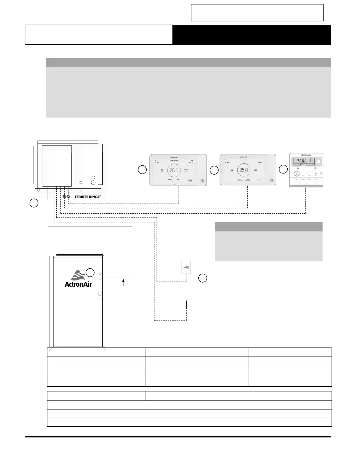
Wiring Confi guration : Recommended
NOTES
• Diagram shown below is a general representation only. Refer to individual unit wiring diagram for complete wiring
connection details.
• Long runs beside Mains cables or TV antenna cables should be avoided where possible.
• Wiring confi guration for LR7-1 and LC7-2 wall controller is the same.
• Daisy connection not allowed for NEO wall controller.
• For the Neo controllers the cable MUST be looped twice through the ferrite ring.
• Ferrite must be installed 50mm to 100mm from the CMI board.
Item Description Maximum Cable Length
1 to 4 Outdoor PCB to Indoor PCB 100 m
4 to 2a, 4 to 2b Indoor PCB to Wall Controller 90 m
4 to 2c Indoor PCB to Wall Controller 3 100 m
4 to 3 Indoor PCB to Remote Sensor 100 m
Description Cable Type
Indoor to Wall Controller Cat5e UTP (AWG 24) Data Cable
Indoor to Remote Sensor Cat5e UTP (AWG 24) Data Cable
Indoor to Outdoor Data Cable 2 Core (1 Pair) Twisted Pair, 7/0.30 (0.5mm
2
) Shielded Data Cable
FERRITE RINGS*
4
LR71
WALL CONTROLLER 3
OPTIONAL
2c
INDOOR UNIT
DATA CONTROL
CABLE
3
LMRS2
OPTIONAL
AERSS
OPTIONAL
OUTDOOR UNIT
1
2a
NEO
WALL CONTROLLER 1
OPTIONAL
2b
NEO
WALL CONTROLLER 2
OPTIONAL
NOTES
The controller wiring MUST be looped twice
through the ferrite ring.
*Ferrite must be installed 50mm to 100mm
from the CMI board.