Installation and Commissioning Guide
Split Ducted Units
PRELIMINARY DATA ONLY Ver. 3.03 220620
THIS LABEL TO BE REMOVED ON SIGN-OFF
25
Installation and Commissioning Guide - Split Ducted Indoor Unit
Doc. No.0525-084 Ver. 3 22xxxx
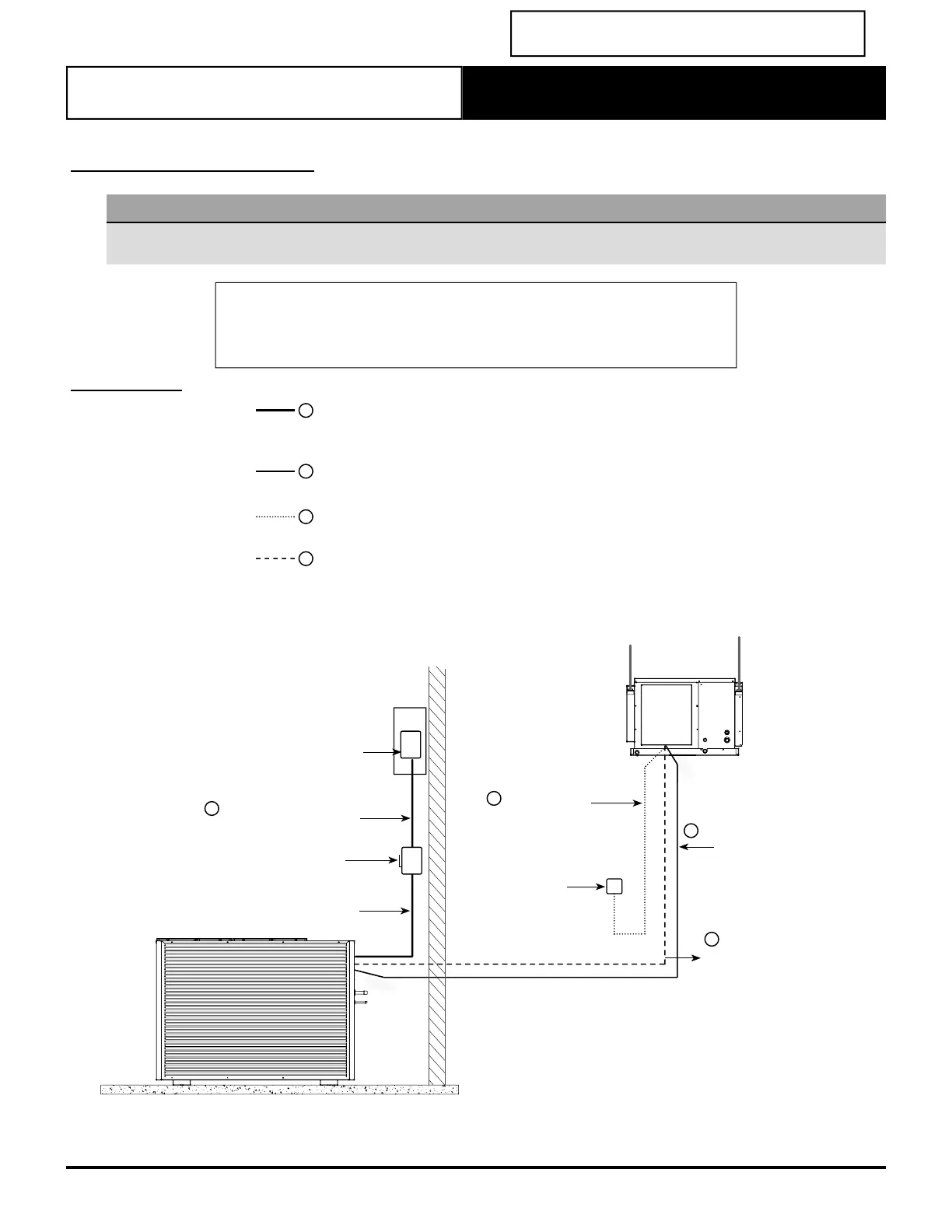
Electrical Connection
NOTES
• To minimise noise interference, Data and Power cable clearance should be maintained as much as possible.
• All drawings are for illustration purposes only. Actual unit may vary depending on the model.
DETAILED WIRING DIAGRAM IS PROVIDED WITH THE UNIT.
Outdoor Unit: Located at the back of electrical/compressor access panel.
Indoor Unit: Located at the back of electrical box cover.
MAINS WIRING (230/400VAC)
(Single Phase + Neutral + Earth) 50Hz
(Three Phase + Neutral + Earth) 50Hz
INTERCONNECTING POWER CABLE 230VAC
(Single Phase + Neutral + Earth) 50Hz
DATA CABLE TO WALL CONTROLLER
(Cat5e UTP (AWG 24) Data Cable)
EXTRA LOW VOLTAGE DATA CONTROL WIRING
(2 Core Shielded Twisted Pair 7/0.30 (0.5mm
2
) Data Cable)
2
1
4
3
SUBMAIN TO UNIT
INDOOR
UNIT
WALL
CONTROLLER
SUBMAINS ISOLATOR
(Field Supplied by Installer)
SUBMAINS
CIRCUIT BREAKER
INTERCONNECTING DATA
CONTROL CABLE INDOOR TO
OUTDOOR
4
DATA CABLE
(Supplied with the unit)
20m
3
INTERCONNECTING
POWER CABLE
OUTDOOR INDOOR
2
MAIN SUPPLY FROM
DISTRIBUTION BOARD
1
OUTDOOR
UNIT
Split Unit