Installation and Commissioning Guide
Split Ducted Units
PRELIMINARY DATA ONLY Ver. 3.03 220620
THIS LABEL TO BE REMOVED ON SIGN-OFF
17
Installation and Commissioning Guide - Split Ducted Indoor Unit
Doc. No.0525-084 Ver. 3 22xxxx
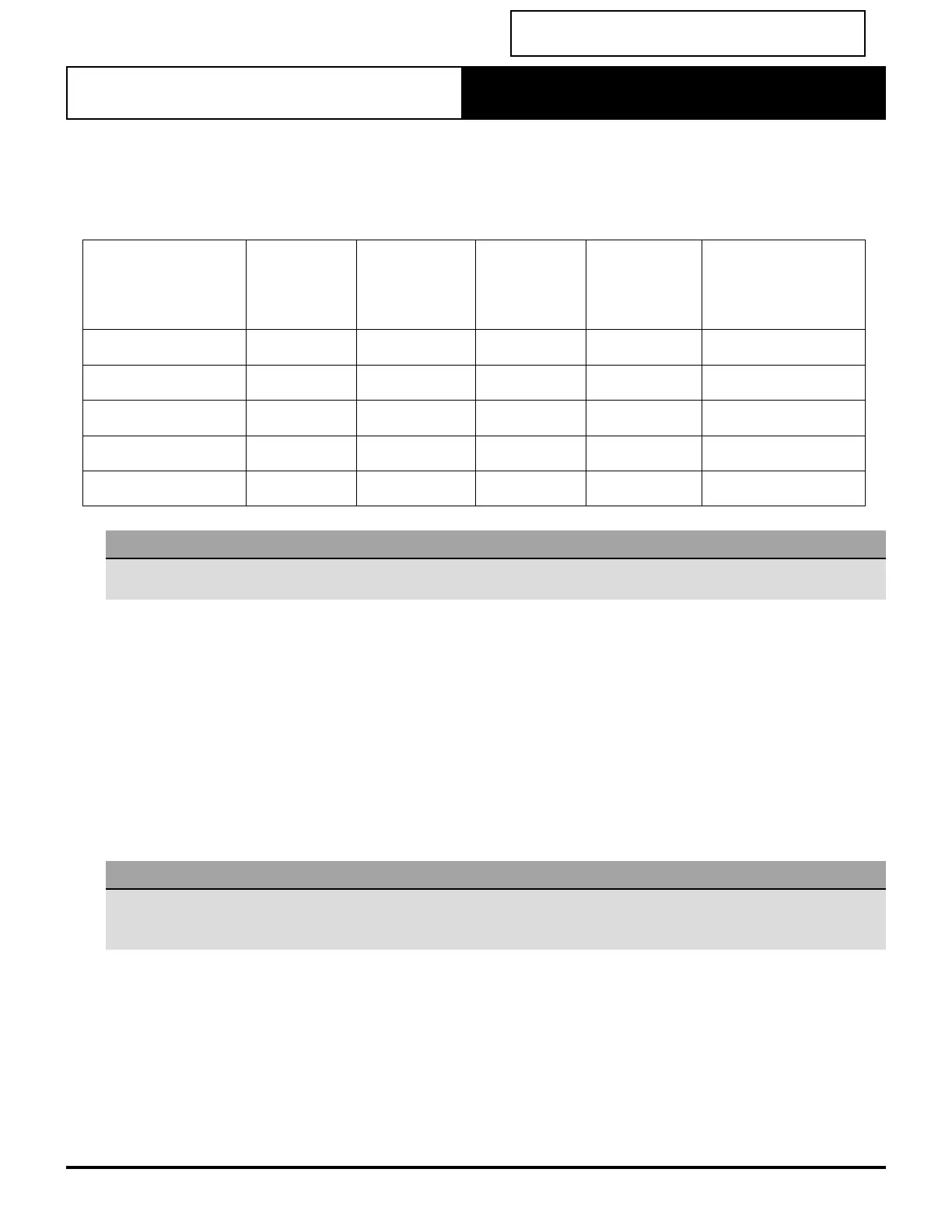
Return Air Grille Sizes
Careful consideration is to be given to pressure drops through return air grilles, air filters and crimped or tight bends in
duct. Grille sizes shown are based on a velocity of 2.5 m/s, sizes shown are free area, please ensure your suppliers are aware
of these requirements.
Model
Nominal
Supply
Air Flow (L/s)
Minimum
Return
Air Grille Sizes
(free area)
Maximum
Supply Air
Flow (L/s)
Minimum
Return
Air Grille Sizes
(free area)
Recommended
Return Air Grilles
(For nominal air
flow)
EVV140S / EFV140S 630 0.26 m
2
900 0.36 m
2
540 x 640 =0.35 m
2
EVV160S / EFV160S 750 0.30m
2
900 0.36m
2
540 x 740 = 0.40m
2
EVV180S / EFV180S 850 0.36m
2
1020 0.41m
2
540 x 890 = 0.48m
2
EVV210S / EFV210S 1020 0.40m
2
1200 0.48m
2
540 x 890 = 0.48m
2
EVV240S / EFV240S 1130 0.44m
2
1320 0.53m
2
540 x 890 = 0.48m
2
NOTE
To achieve maximum airflow you may need to upsize your return air grille one size larger than our ‘Recommended Return Air
Grilles’ shown above.
Care must be taken to identify return air paths for each zone for minimal static. This may include undercut doors or
additional return air duct and grilles.
Other Guidelines
• Larger master bedrooms or parents retreats may have privacy issues with undercut doors, so a separate return duct or
transfer duct may be needed. The use of walk in robes for positioning of return air grilles allows for a better finish.
• Special attention may also be required in home theaters where rooms are sealed for noise breakout. A dedicated return
air duct with zone barrel linked to the supply air zone barrel may be required in this case.
• Small critical areas such as a study, which are below the minimum air flow and duct sizing, would need to be coupled
with another area.
• Dual Master controllers are also recommended for two storey homes or larger single storey homes.
Variable Airflow Test
NOTES
• Test to be completed on zoned systems after commissioning of the fan is completed.
• Zone 1 has been used as an example. Applications where the system has been designed to cool only selected zones at any
one time, airflow may differ. For these applications complete test on a zone selected during the fan commissioning process.
1. Open all available zones and select AUTO fan mode on the wall control.
2. Allow 3 minutes for fan to adjust speed.
3. Check airflow at any outlet from Zone 1.
4. Close all zones except Zone 1.
5. Allow 3 minutes for fan to adjust speed.
6. Check airflow at the same outlet.
7. The airflow at this outlet should remain reasonably constant.
8. Switch to the manual mode HIGH.
9. A significant increase in airflow should be noted.
10. Switch to medium, then low and note airflow drops accordingly.