35
Source AC Control Connections (cont.)
connector will be set to zone tracking. Any number of ACC-3s can be connected to the DB-9
via a two conductor low voltage cable. Since the ACC-3 has its own AC line cord, it can be
located anywhere in the house and triggered through the two conductor low voltage wire
which is significantly easier to run long distances than high voltage wire.
Instead of setting jumper pins, as with the ACC-48, the ACC-3's low voltage feed is connected
to specific terminals on the DB-9. One terminal is for ground (-) and is used for all zones. The
second connector is for voltage (+) and is zone specific. For example, if an external power
amplifier is on zone 2, the two conductor wire running to that amplifiers ACC-3 is connector
to pins 1 & 4 on the DB-9.
To setup the Delta-88 for use with a DB-9 or even an ACC-
48 for zone tracking follow these steps.
a. Plug the Delta-88 into an AC outlet.
b. Turn on the Delta-88 by first selecting a room
button and then any source button. The Delta-88's
"Source Display" will first read "POWER UP" fol-
lowed by the selected source name.
c. To enter the program mode, press and hold the
LABEL button until its LED is lit. Please note, the
Delta-88 will automatically time out of the pro-
gram mode if no functions are selected.
d. Keep pressing the PRESET button until the "Source
Display" reads MODE 2 SETUP.
e. Press and hold the LOUDNESS button. The
"Source Display" will change between
"DB9=ROOMS" and "DB9=SOURCES". Release
the LOUDNESS button while the display reads
"DB9=ROOMS".
f. Press the LABEL button to exit the programming
mode or allow the Delta-88 to time out.
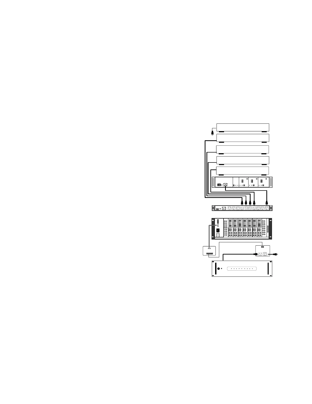
When using the DB-9, the following pin numbers correspond to the Delta-88's eight rooms.
Please note, the DB-9 may be labeled incorrectly with respect to room numbers. The following
chart should be used to provide low voltage to the ACC-3 for power to external amplifiers.
DB-9 Pin 1 - Common Ground (- DC) for All 8 Rooms
DB-9 Pin 2 - Room 4 Positive (+5VDC) When Room 4 Is On
DB-9 Pin 3 - Room 3 Positive When Room 3 Is On
DB-9 Pin 4 - Room 2 Positive When Room 2 Is On
DB-9 Pin 5 - Room 1 Positive When Room 1 Is On
DB-9 Pin 6 - Room 5 Positive When Room 5 Is On
DB-9 Pin 7 - Room 6 Positive When Room 6 Is On
DB-9 Pin 8 - Room 7 Positive When Room 7 Is On
DB-9 Pin 9 - Room 8 Positive When Room 8 Is On
Low Voltage Out
DB-9
To Delta
ACC-3
1234
-A+ -B+
115 V
1
2
3
4
1
2
3
4
1
2
3
4
MULTI-TUNER
MT-3000
AUDIO OUT
LR
AUDIO OUT
LR
AUDIO OUT
LR
AUDIO OUT
LR
REMOTE REMOTE REMOTE REMOTE
ANT PRE-AMP
ANT PRE-AMP
ANT PRE-AMP
ANT IN
ANT IN ANT IN
COMBINED
OUTPUT
TUNER 3 TUNER 2 TUNER 1
VOLTAGE SELECT
FUSE
AC POWER
CD CHANGER
LASER
CASSETTE CHANGER
DSS
VCR
VCR
TO
AC
FIX
VAR
SPEAKER
LR
+
-
LINE
RAM-50
1
2
3
4
5
6
7
8
AUDIO
INPUTS
FIX
VAR
SPEAKER
LR
+
-
LINE
RAM-50
FIX
VAR
SPEAKER
LR
+
-
LINE
RAM-50
FIX
VAR
SPEAKER
LR
+
-
LINE
RAM-50
FIX
VAR
SPEAKER
LR
+
-
LINE
RAM-50
FIX
VAR
SPEAKER
LR
+
-
LINE
RAM-50
FIX
VAR
SPEAKER
LR
+
-
LINE
RAM-50
432121
ADA BUS™
MUTE L.V.
ZONE L.V.
OUT
AC INPUT
AC
LOOP OUT
TO DELTA-88
1
2
1
2
3 4
34
56
56
7
8
7
8
VSM-8
VIDEO SWITCHER
V
I
D
E
O
I
N
P
U
T
V
I
D
E
O
O
U
T
P
U
T
ON
OFF
POWER
PF-200
F
U
S
E
F
U
S
E
F
U
S
E
ACC-3000
1234
ACC-3000
FUSE
AC POWER
SWITCHED B
SWITCHED A
8
7
6
5
4
3
2
1
ADA BUS
LOW VOLTAGE WIRE
ACC-3
DB-9