132
GND
(Shield)
TX
RX
GND
TRANSMIT
RECEIVE
STEREO
PLUG
SHELL
POWER (FROM ANT.
PRE-AMP JACK)
PIGTAIL SHOULD BE
APPROX. 1 FOOT LONG
PIN 1 (GND)
PIN 4
PIN 2
PIN 3
115 V
1
2
3
4
1
2
3
4
MULTI-TUNER
MT-3000
AUDIO OUT
LR R
AUDIO OUT
LR
AUDIO OUT
LR
REMOTE REMOTE REMOTE REMOTE
ANT PRE-AMP
ANT PRE-AMP
ANT PRE-AMP
ANT IN
ANT IN ANT IN
COMBINED
OUTPUT
TUNER 3 TUNER 2 TUNER 1
VOLTAGE SELECT
FUSE
AC POWER
GND
(Shield)
POWER
(PIGTAIL IS AT LEAST
1 FOOT IN LENGTH)
TX
RX
GND
TRANSMIT
RECEIVE
PIN 1=GROUND (Shield)
PIN 2=TRANSMIT
PIN 3=RECEIVE
PIN 4=POWER
3 CONDUCTOR, 16 GAUGE,
BRAIDED SHIELD CABLE.
BELDEN #9953
TO BI-3000
TO MT-3000
(COMBINED REMOTE JACK)
STEREO
PLUG
SHELL
#4
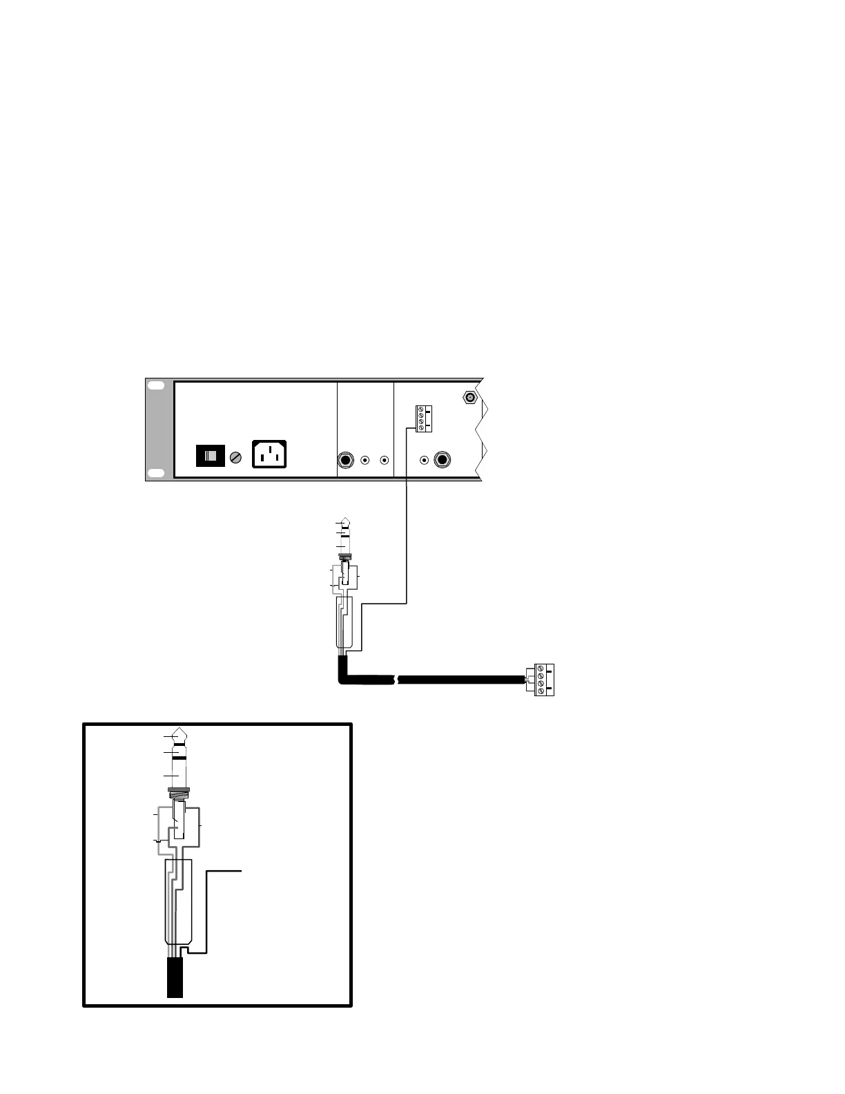
The MT-3000 Multi-Tuner is an ADA Bus™ component, as well, but it does not have
the standard four-pin receptacle on its rear panel. The ADA Bus™ information is sent and
received through the COMBINED OUTPUT REMOTE jack on the MT-3000. Because the MT-
3000 doesn't utilize the standard four-pin screw terminal connector, you must use the special
connecting wire included with the System Titanus so that the tuner can be attached to a BI-3000.
Refer to the following illustrations when making this ADA Bus™ connecting wire for the MT-
3000.
NOTE:
All ADA Bus™ connections must be made with three-conductor, braided shield wire; 16 gauge
(BELDEN # 9953).
MT-3000
Appendix K
MT-3000 Multi-Tuner
Connecting an MT-3000 Multi-Tuner to the ADA Bus™