134
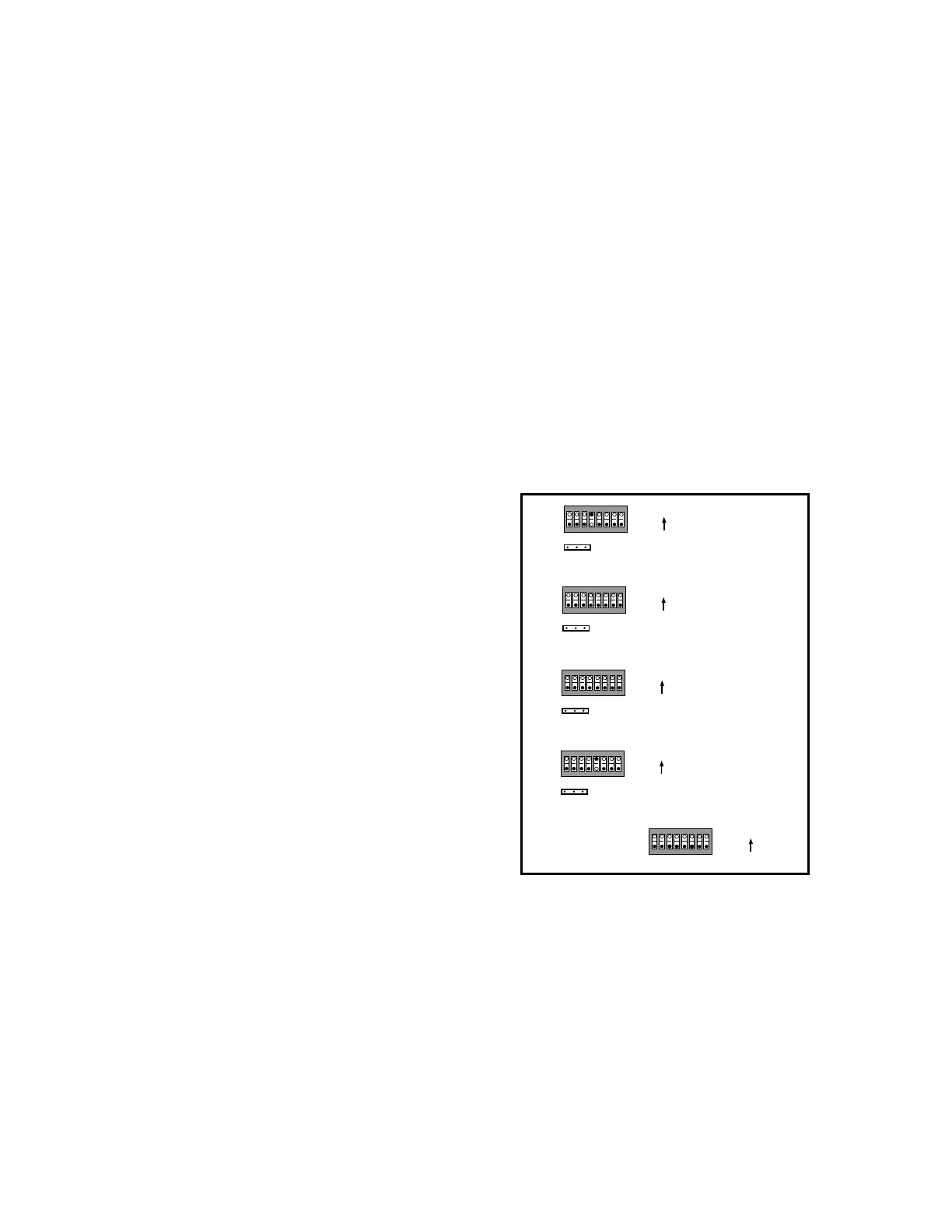
12345678
SW5
12345678
SW4
N/A
N/A
ADA TXD
ADA RXD
EXT IRR 4
EXT IRR 3
EXT IRR 2
EXT IRR 1
GND
OPT 1
OPT 2
12345678
SW3
GND
OPT 1
OPT 2
ON
ON
ON
12345678
SW2
GND
OPT 1
OPT 2
12345678
SW1
GND
OPT 1
OPT 2
ON
ON
1=ON
0=OFF
1=ON
0=OFF
1=ON
0=OFF
1=ON
0=OFF
1=ON
0=OFF
A) Remove the cover of the PCT-4 by taking out the
four corner screws. Pull out the unit, then remove the
remaining screws from the cover. At this point, you
can pull the bigger board off, thus exposing the D.I.P.
switches.
SW 1 - SW 4
B) Refer to the sheet entitled “PCT-4 Library” to select
the STANDARD transport function option for the
specific piece of source equipment that you want to
control. Keep in mind that 1=ON and 0=OFF (OPEN).
Even though you have set the D.I.P. switch for the
single STANDARD function, the other functions listed
for the particular piece of source equipment on the
library sheet will be performed, as well. This type of
multi-function transport operation is called Advanced
Transport Control.
SW 5
C) Make sure that positions 3 and 4 on SW 5 (labelled ADA TXD and ADA RXD) are both
on. If you want to control a piece of source equipment with its original remote control, as well
as from the MC-3000 keypad, you could do this by selecting the appropriate EXT IRR position
on SW 5. For example, if you wanted to control the source unit connected to CODE OUT 1 with
its remote control, put SW 5, position 8 in the ON position. For most applications, positions 5
through 8 should be on.
NOTE: If the MC-3000 control is mounted in a room with a lot of
fluorescent lighting, a problem might occur if the EXT IRR control is activated on SW 5
because of extraneous interference caused by the fluorescents. To remedy this type of
problem, simply make sure that positions 5 through 8 on SW 5 are OFF (OPEN).
D) When you are finished programming SW1 - SW5, re-assemble the unit and replace the front
cover and screws.
IMPORTANT: Before making any changes to the D.I.P. switch settings within the PCT-4,
make sure to disconnect the four-pin ADA Bus™ connector, thus cutting power to the unit.
Also, you will know which revision of the “PCT-4 Library” sheet to refer to when making the
D.I.P. switch adjustments by making sure that the revision number at the top of the library
sheet corresponds to the revision number on the microprocessor chip in the PCT-4.
Each of the mini-pin ports on the PCT-4 has a corresponding set of D.I.P. switches. Each
set of switches can be used to control the transport functions on the piece of source equipment
that is connected to it. These transport functions are activated with the transport control
buttons on the MC-3000 music control. To set the D.I.P. switches labelled SW1-SW5, which are
located inside the PCT-4, follow these steps:
Appendix L
PCT-4 Basic Source Controller
Setting and Adjusting a PCT-4