ALPHA® Solar™ Sign
22 Installation: Electrical connection
Signal wiring
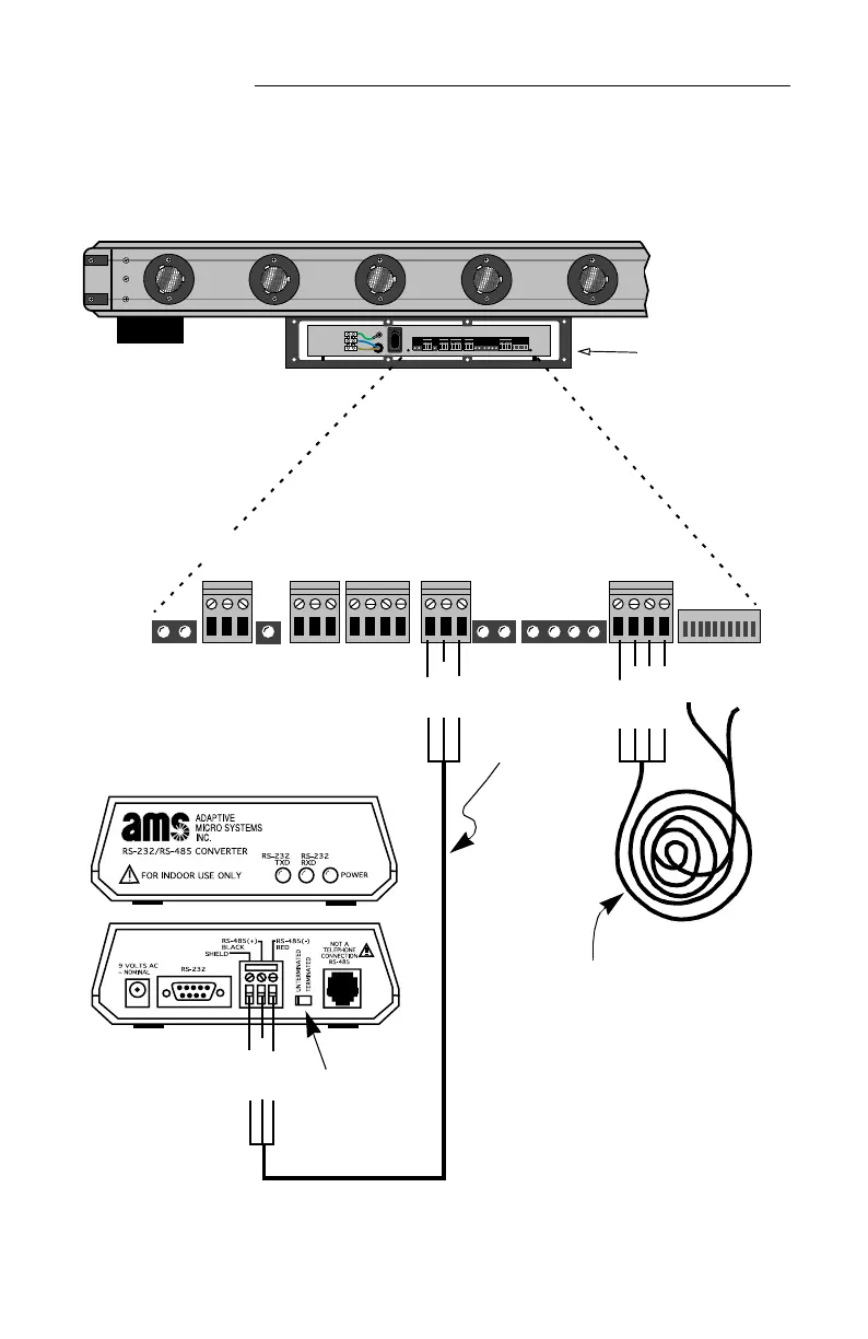
5. To connect the sign so messages can be sent to it by a computer,
run RS485 signal wire (pn 1088-8000) through the signal conduit:
12345678910
1
0
12345678910
Figure 6: Alpha® Solar™ (bottom view) — RS485 and temperature probe connections
RED (-)
BLACK (+)
SHIELD
SHIELD
BLACK
(+)
Converter Box III (pn 1088-1111)
The converter box must be installed indoors.
RS485
cable
Run all signal cables
(OUTPUT RELAY, ISO
OUT, RS232, RS485,
and EXTERNAL TEMP
PROBES) through the
opening in this side.
RS485RS232
EXTERNAL
TEMP.
PROBES
OUTPUT
RELAY
ISO
RED wire
BLACK
wire
Green wire
Temperature probe (optional)
• Run the temperature probe cable
through the signal conduit.
• Mount in an area which best represents
the open air temperature.
• The ends of the temperature probe
should be mounted out of doors in a
shaded location and NOT in direct
sunlight.
• When mounted, the ends of the
temperature probe should be suspended
in the air and not touch anything.
Set switch to
Unterminated.