RM244V & CS4 User Manual
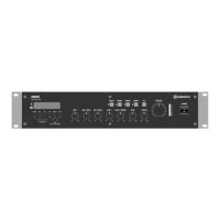
Speaker outputs
The RM244V has 4 separate outputs for connecting 100V line speakers. These are arranged on a
single modular connector for convenience. Each output has 2 screw terminal connections.
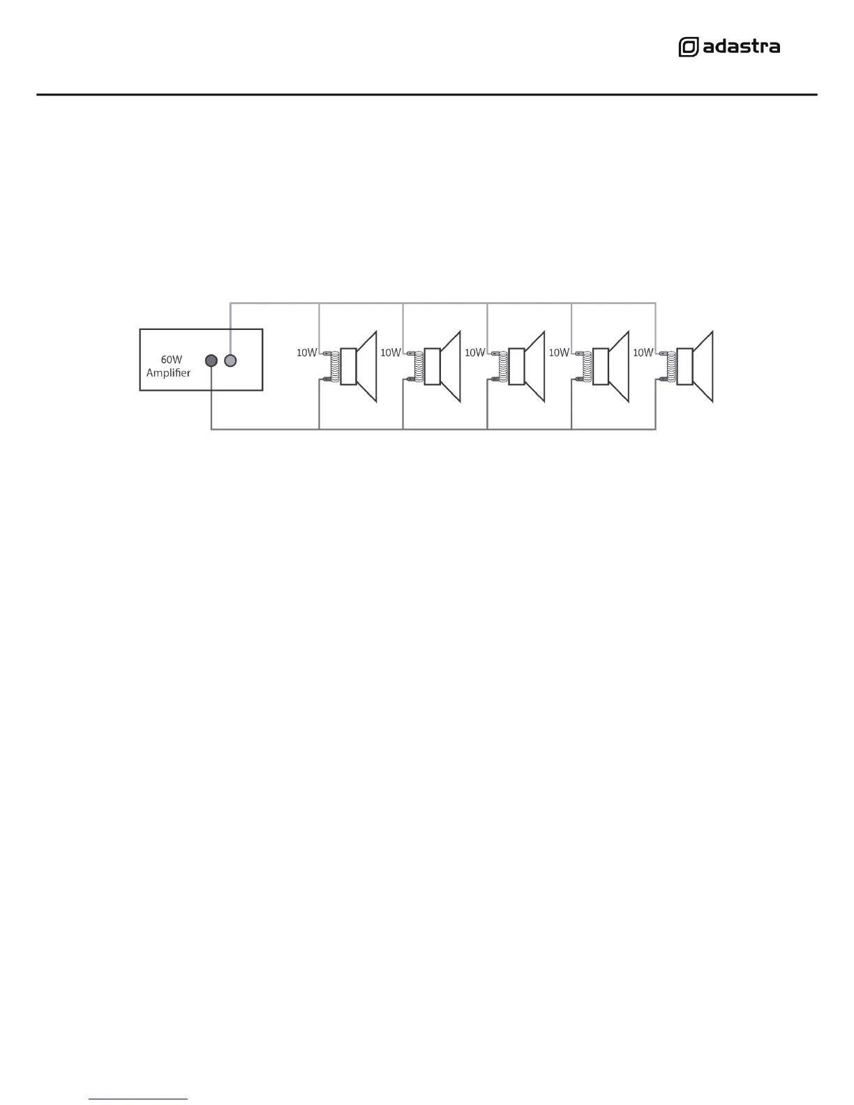
For each zone output, connect the “100V” output terminal to the positive (+) connection of the
speaker and “COM” output to the negative (-) connection of the speaker. Connect further speakers in
parallel to the first speaker with all positive terminals and connected together and all negative
terminals connected together as shown below.
Repeat this process for all 4 zone outputs as required. Usually, each zone represents a specific room
or area and connecting these separately will allow individual control and paging for each zone.
A 100V line speaker system can comprise of many speakers connected together. The determining
factor for how many speakers can be used on a single amplifier is the power rating. For most
purposes, it is advised to connect as many speakers as needed with a combined wattage of no more
than 90% of the amplifier’s output power rating.
In the case of the RM244V, the maximum power output is 240W, shared across all 4 zones. This
means that a recommended maximum 216W combination of speakers can be connected to a single
zone or shared across all 4 zones (so long as the total does not exceed 216W)
Emergency 24V contacts
For fire alarm panels with 24V trigger out, connect to the trigger to the 24V contacts on the RM244V.
When the fire alarm is activated, 24V trigger on these terminals will mute all except CS4 call stations.
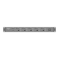
Connecting a CS4 call station
The CS4 call station is a bespoke optional addition to the RM244V system and up to 2 of these can
be connected to a single amplifier by RJ45 with CAT5 network cable. This is not a standard LAN
connection and should only be connected directly to the RM244V.
The CS4 call station comprises a base unit and paging microphone. Connect the microphone to the
XLR input on top of the base unit.
Connect the RJ45 connector on the rear panel of the CS4 to one of the RJ45 inputs on the rear of the
RM244V. The CAT5 cable carries power to the CS4 and control and audio signals to the RM244V.
If the CAT5 cable run is further than 100m, it will be necessary to connect 24Vdc power to the DC
jack of the CS4 for operation up to 1000m cable length.