Advanced
®
Micro-Osmometer Model 3320 User’s Guide
a sample port to precisely position each sample for the osmolality test,
a high-precision thermistor
probe, measurement and control circuitry,
a power supply, and a user interface which includes the message dis-
play panel. The function of many of these parts is described below.
Electronic circuits (inside)
The main circuitry is contained on two printed circuit boards in a moth-
erboard/daughterboard configuration. More in-depth technical details
are available in the unit service manual, sold separately.
I/O Board: Provides an interface between the external connectors and
the application board.
8
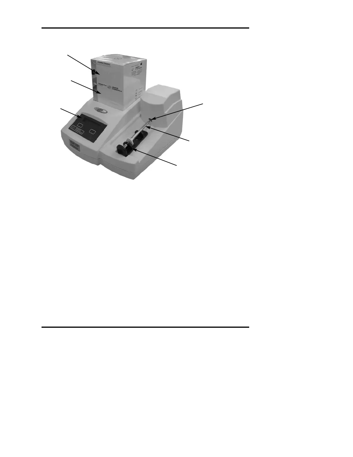
Figure 3: Model 3320 Components and Controls
Display
Panel
Operating
Cradle
Sampler
Cooling
Chamber
(inside)
Chamber
Cleaners
Sampler
Tips