www.advancedco.com
6
The AV-VBM audio panel w/microphone and AV-VB distributed audio booster are designed to be powered from 120
– 240VAC at 50/60 Hz. Each unit incorporates two (2) electrically independent Class A or B amplifier speaker
circuits, rated 40 Watts per amplifier circuit maximum. Speaker circuit requirements are 25 VRMS.
Note: For 70 VRMS installations refer to Advanced’ AV-V70 Universal Audio Converter Installation &
Operational Panel PN: 682-044.
The AV-SM switch/LED module of the AV-VBM audio panel w/microphone provides a power LED, two trouble LEDs
(power supply charger and audio amplifier) visible with the outer door closed and three toggle switches (play
message one, play message two and push down/hold for all-call). In addition, the AV-SM switch/LED module
provides terminals for host fire alarm control panel monitoring interface. An optional AV-ZS-CM AV splitter switch
module is available for installations utilizing the Advanced’ optional AV-ZS amplifier speaker circuit zone splitter
module.
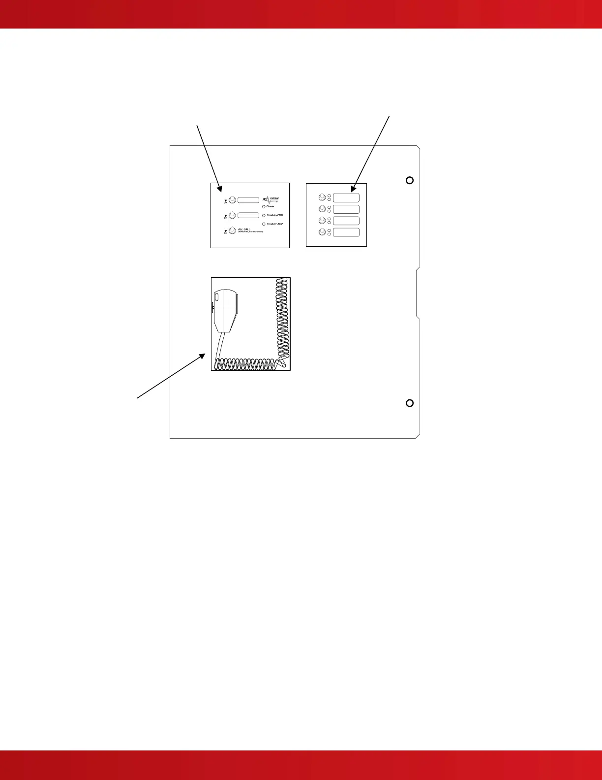
Figure 2 – AV-VBM Inner Door Shown with Microphone and AV-SM (Switch/LED Module)
(Also Shown with Optional AV-ZS-CM [AV Splitter Switch Module])
AV-MIC
(Microphone Assembly)
AV-SM (Switch/LED Module)
(Includes Power LED, Trouble LEDs,
Message Switches and All Call Switch)
Optional AV-ZS-CM
(AV Splitter Switch Module)
 Loading...