115 ADAM-6200 User Manual
Chapter 4 System Configuration
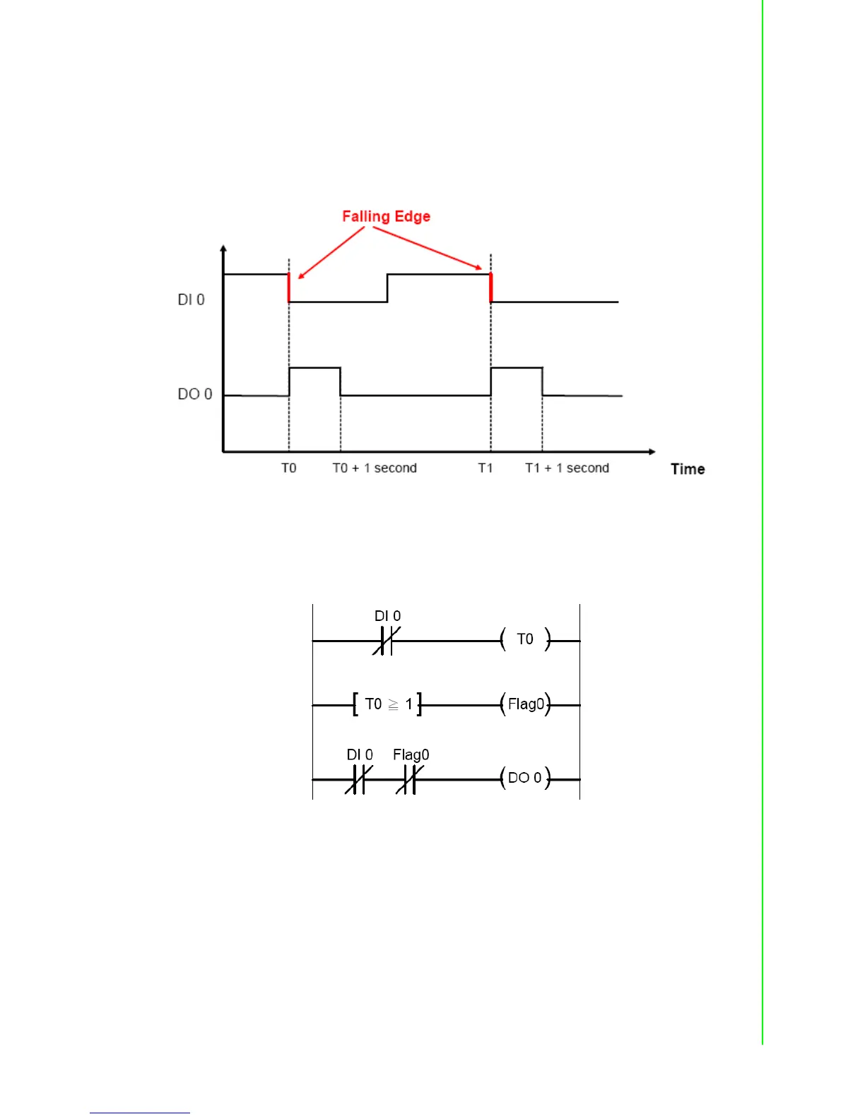
7. Falling Edge
For Falling Edge application, the DO value will be activated to logic high, when DI
value is changing from logic high to logic low (it is so-called falling edge). But the DO
value won't continuously remain logic high. Instead, after a specific period (in the
example project, it is 1 second), the DO value will back to logic low. The time chart is
shown as below:
You can see the DO 0 will only be triggered when falling edge of DI 0 occurs. In the
example project we provide, the DO status will remain logic high for 1 second. Then it
will back to logic low. When PLC is used for this kind of application, the ladder dia-
gram will be likely as below:
 Loading...