19 PCA-6781 User Manual
Chapter 2 Installation
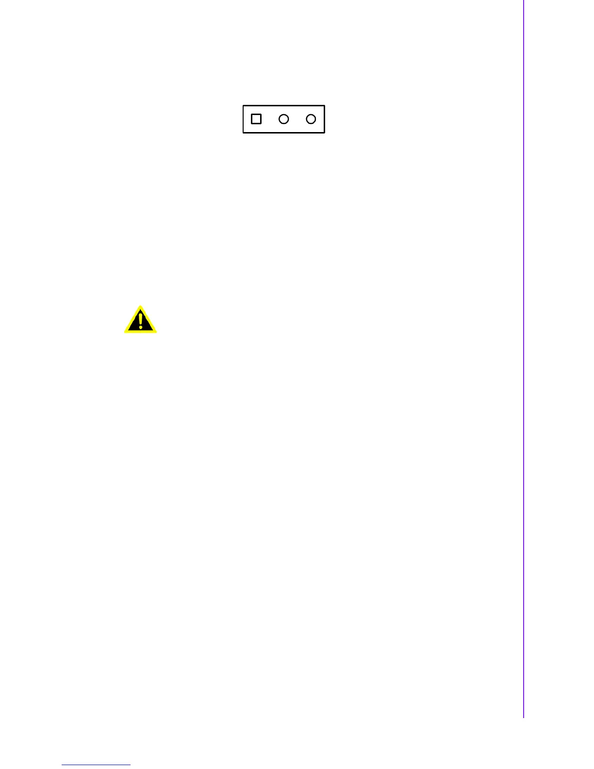
2.24 ATX Suspend Power connector(CN23)
The PCA-6781 can support an advanced soft power switch function, if an ATX power
supply is used. To enable the soft power switch function:
1. Get the specially designed ATX-to-EBX power cable
2. Connect the 3-pin plug of the cable to CN23 (ATX feature connector).
3. Connect the power on/off button to CN1.
Default value is set CN23 to short pin1-2.
Important Make sure that the ATX power supply can take at least a 10 mA load on the
5 V standby lead (5 VSB). If not, you may have difficulty powering on your system.
2.25 System FAN connector (CN25)
The PCA-6781 is equipped with a 3-pin FAN connector providing +12 V power for
system FAN.
2.26 SMBus connector (CN26)
The PCA-6781 is equipped with a 4-pin SMBus connector providing SMBus for
peripheral usage.
2.27 Hardware Fail LED (CN27)
The PCA-6781 is equipped with 2-pin hardware fail pin header to connector with
LED. If you connect CN27 with LED, LED will light when buzzer on PCA-6781 has a
warning noise.
Warning! If the board is used under AT Mode, besides setting J3 to AT Mode,
please also make sure PCA-6781’s CN23 PIN1 and PIN2 should be
connected to jumper for stable V5REF_Sus voltage supply. CN23
default value is set to short PIN1 and PIN2.
1 23