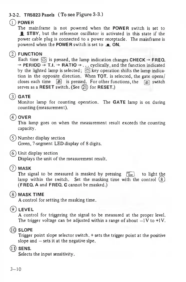
0 POWER
The mainframe is not powered when the POWER switch is set to
JL STBY, but the reference oscillator is activated in this state if the
power cable plug is connected to a power receptacle. The mainframe is
powered when the POWER switch is set to ON.
@ FUNCTION
Each time (o) is pressed, the lamp indication changes CHECK -* FREQ.
-* PERIOD T.l. -»• RATIO . .. cyclically, and the function indicated
by the lighted lamp is selected; 0 key operation shifts the lamp indica
tion in the opposite direction. When TOT. is selected, the gate opens/
closes each time ® is pressed. For other functions, the (g switch
serves as a RESET switch. (See 0 for RESET.)
0 GATE
Monitor lamp for counting operation. The GATE lamp is on during
counting (measurement).
0 OVER
This lamp goes on when the measurement result exceeds the counting
capacity.
0 Number display section
Green, 7-segment LED display of 8 digits.
0 Unit display section
Displays the unit of the measurement result.
0 MASK
The signal to be measured is masked by pressing [^T| to light the
lamp within the switch. Set the masking time with the control 0
(FREQ. A and FREQ. C cannot be masked.)
0 MASK TIME
A control for setting the masking time.
© LEVEL
A control for triggering the signal to be measured at the proper level.
The trigger voltage can be adjusted within a range of about —IV to +1V.
@ SLOPE
Trigger point slope selector switch. + sets the trigger point at the positive
slope and - sets it at the negative slpe.
(fl) SENS.
Selects the input sensitivity.
3-2-2. TR5823 Panels (To see Figure 3-3.)
3-10