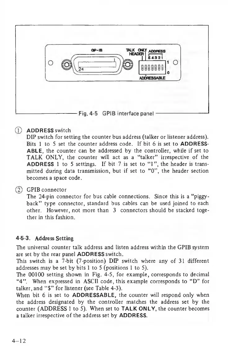
(7) ADDRESS switch
DIP switch for setting the counter bus address (talker or listener address).
Bits 1 to 5 set the counter address code. If bit 6 is set to ADDRESS
ABLE, the counter can be addressed by the controller, while if set to
TALK ONLY, the counter will act as a “talker” irrespective of the
ADDRESS 1 to 5 settings. If bit 7 is set to “1”, the header is trans
mitted during data transmission, but if set to “0”, the header section
becomes a space code.
(2) GPIB connector
The 24-pin connector for bus cable connections. Since this is a “piggy
back” type connector, standard bus cables can be used joined to each
other. However, not more than 3 connectors should be stacked toge
ther in this fashion.
4-5-3. Address Setting
The universal counter talk address and listen address within the GPIB system
are set by the rear panel ADDRESS switch.
This switch is a 7-bit (7-position) DIP switch where any of 31 different
addresses may be set by bits 1 to 5 (positions 1 to 5).
The 00100 setting shown in Fig. 4-5, for example, corresponds to decimal
“4”. When expressed in ASCII code, this example corresponds to “D” for
talker, and “$” for listener (see Table 4-3).
When bit 6 is set to ADDRESSABLE, the counter will respond only when
the address designated by the controller matches the address set by the
counter (ADDRESS 1 to 5). When set to TALK ONLY, the counter becomes
a talker irrespective of the address set by ADDRESS.
4-12
 Loading...