IST5 Tower UPS 10kVA~40kVA User Manual 21
Trigger EPO when disconnect with J4-2
Trigger EPO when connect with J4-3
Generator Input Dry Contact
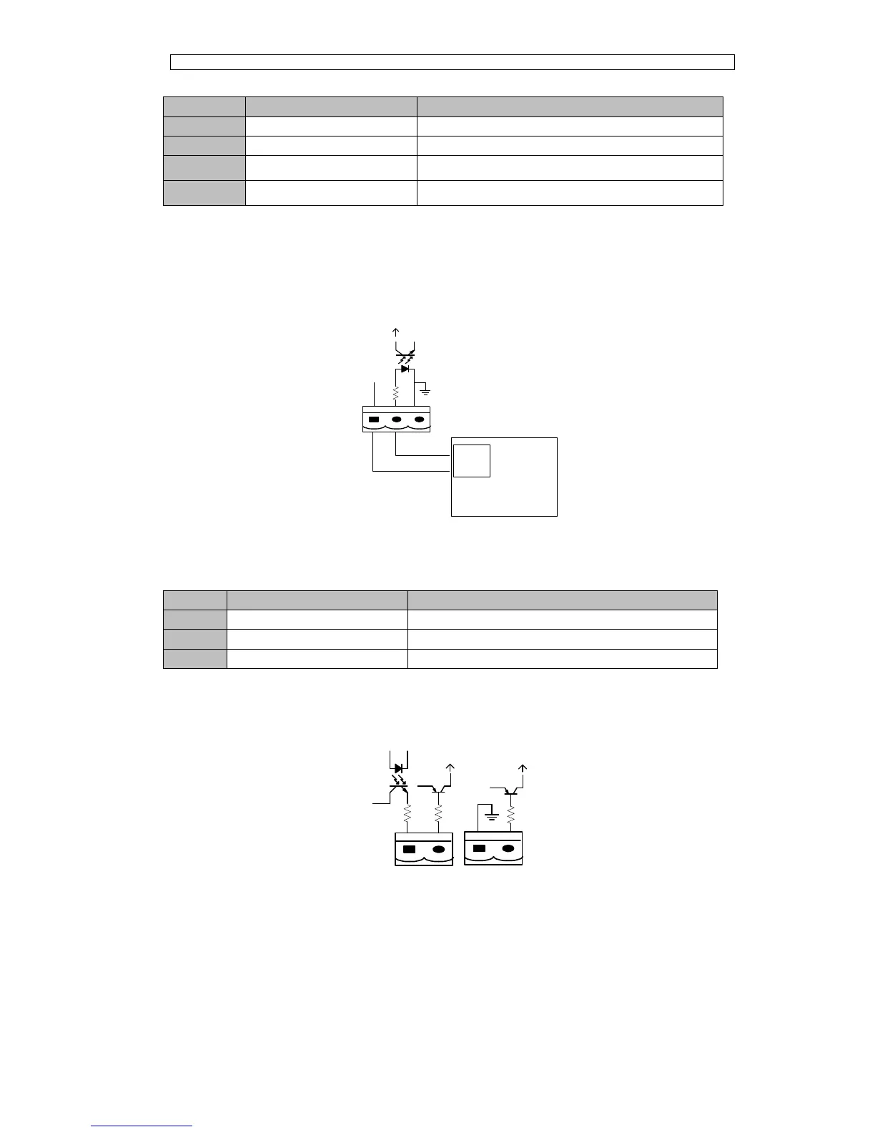
The default function of J5 is the interface for generator J5 Connect pin 2 of J5 with
+24V power supply; it indicates that the generator has been connected with the system.
The interface diagram is shown in Fig.3-16, and interface description is shown in Table
3.8.
J5
GEN
+24V
AUX-N.O.
AUX-N.O.
Generator
Fig. 3-16 Diagram of status interface and connection of generator
Table 3.8 Description of status interface and connection of generator
Connection status of generator
BCB Input Port
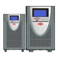
The default function of J6 and J7 are the ports of BCB. The port diagram is shown in
Fig.3-17, and description is shown in Table 3.9.
BCB_DRV
BCB_CONT
J6
J7
BCB_ONL
+24V
+24V
+24V
Fig.3-17 BCB Port
Table 3.9 Description of BCB port