5.5.2 Parallel system setting
Parallel system connection
For field installation, please connect the cables according to Fig.5-6 and Fig.5-8.
In order to assure that all units are equally utilized and to comply with relevant
wiring rules, the following requirements apply:
1. All units shall be of the same rating and must be connected to the same bypass
source.
2. The bypass and the main input sources must be referenced to the same neutral
potential.
3. Any RCD (Residual Current detecting device), if installed, must be of an
appropriate setting and located upstream of the common neutral bonding point.
Alternatively, the device must monitor the protective earth currents of the system.
Refer to the High Leakage Current Warning in the first part of this manual.
4. The outputs of all UPS must be connected to a common output bus.
Parallel system software setting
To change the parallel system setting, please follow the steps below.
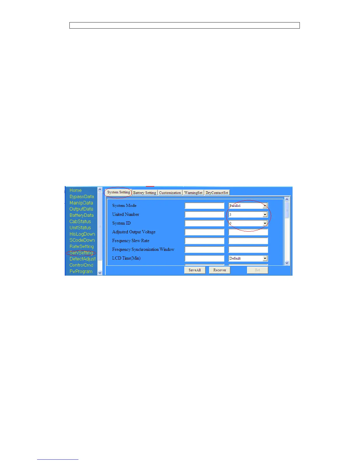
With the monitoring software from manufacturer, select the page of
“Service Setting” as below,
Set “System Mode” to “Parallel”, and set the “United Number” to the number of
units in parallel. For the setting of system ID with a system of 3 units in parallel,
for example, set the number from 0 to 2 for these 3 units accordingly.
Restart the UPS when finish the setting and press the button of “Set”. Here the
software setting is done. Ensure all the output parameters must be set the same.
Parallel system jumper setting
There are different setting of the jumpers on the parallel board and control board
for different parallel system.
The location of connectors on parallel board is shown in Fig.5-11 and control
board in Fig.5-12.