Installation Instruction
4 IST5 Tower UPS 10kVA~40kVA User Manual
2. Product Introduction
2.1 System Configuration
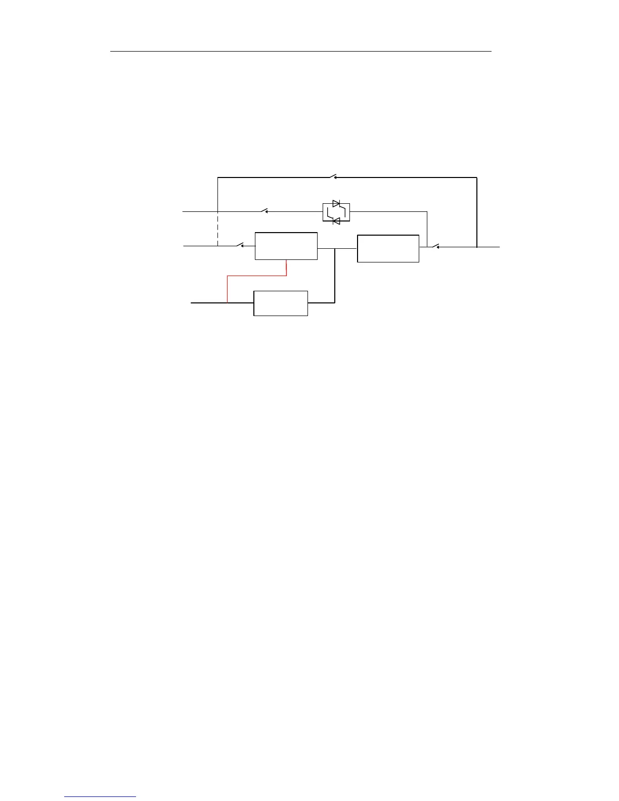
The Tower UPS is configured by the following part: Rectifier, Charger, Inverter, Static
Switch and Manual Bypass Switch. One or several battery strings should be installed to
provide backup energy once the utility fails. The UPS structure is shown in Fig. 2-1.
Fig. 2-1 UPS Configuration
2.3 Operation Mode
The Modular UPS is an on-line, double-conversion UPS that permits operation in the
following modes:
Normal mode
Battery mode
Bypass mode
Maintenance mode (manual bypass)
ECO mode
Auto-restart mode
Frequency Converter mode
2.3.1 Normal Mode
The inverter of power modules continuously supply the critical AC load. The
rectifier/charger derives power from the AC mains input source and supplies DC power
to the inverter while simultaneously FLOAT or BOOST charging its associated backup
battery.