EasyManua.ls Logo

AEC IST5015 - Page 27

Default Icon
57 pages
Print Icon
To Next Page IconTo Next Page
To Previous Page IconTo Previous Page
Loading...
IST5 Tower UPS 10kVA~40kVA User Manual 23
Installation Instruction
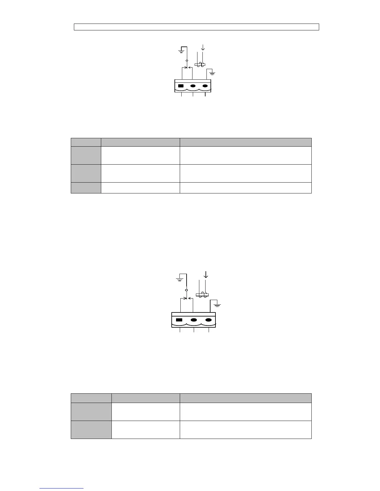
Fig.3-19 Integrated warning dry contact interface diagram
Table3.11 General alarm dry contact interface description
Port
Name
Function
J9-1
GENERAL_ALARM_NC
Integrated warning relay (normally closed) will be
open during warning
J9-2
GENERAL_ALARM_NO
Integrated warning relay (normally open) will be
closed during warning
J9-3
GENERAL_ALARM_GND
Common terminal
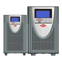
Utility Fail Warning Output Dry Contact Interface
The default function of J10 is the output dry contact interface for utility failure warning,
when the utility fails, the system will send a utility failure warning information, and
provide an auxiliary dry contact signal via the isolation of a relay. The interface diagram
is shown in Fig.3-20, and description is shown in Table 3.12.
Fig.3-20 utility failure warning dry contact interface diagram
Table 3.12 Utility failure warning dry contact interface description
Port
Name
Function
J10-1
UTILITY_FAIL_NC
Mains failure warning relay(normally closed) will
be open during warning
J10-2
UTILITY_FAIL_NO
Mains failure warning relay (normally open) will be
closed during warning
J9
ALARM_NC
ALARM_NO
GND
J10
UTI_FAIL_NC
UTI_FAIL_NO
GND

Related product manuals