IST5 Tower UPS 10kVA~40kVA User Manual 47
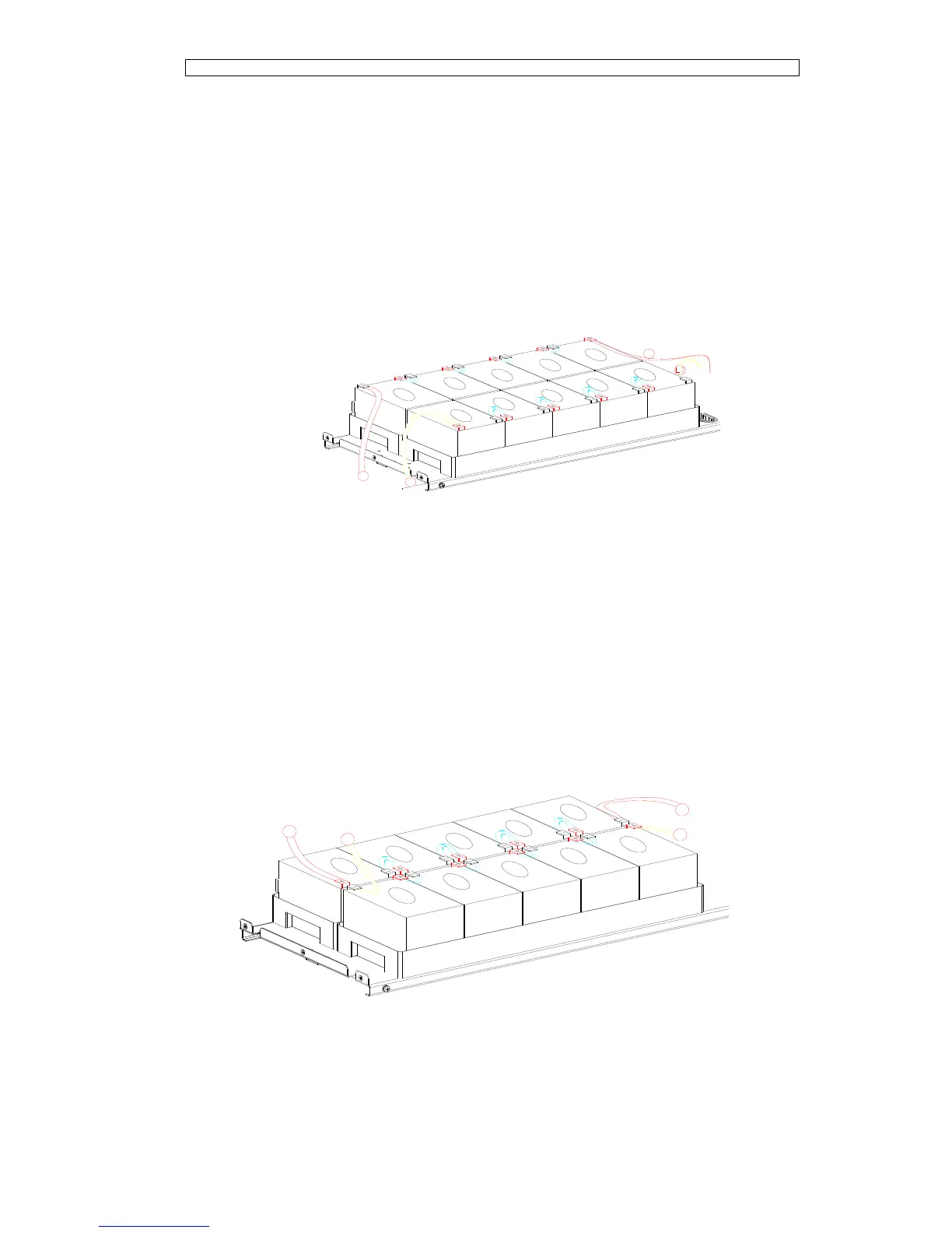
There are 8 groups of batteries in series, with 5 cells for each group. The
interconnection among groups is via cable with Anderson Socket.
Layer 1. The positive of the battery 1# is connected to battery breaker CB4-2, via
the cable labeled L1, and the negative of battery 40# is connected to CB4-6, via the
cable labeled L2, as shown in Fig.6-2.
Fig.6-2-2 Cable connection of Lay 1
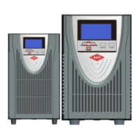
Layer 2. The positive of the battery 6# is connected to the negative of battery 5#,
via the cable labeled L4, and the negative of battery 35# is connected to the positive
of battery 36#, via the cable labeled L4, as shown in Fig.6-3.
Fig.6-2-3 Cable connection of Lay 2