10
Digital Transformer Ratiometer DTR
®
Model 8500
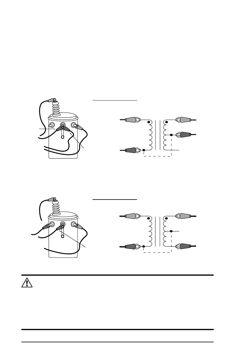
4.3 VT/PT
4.3.1 VT/PT Example Connections
Here is an example of connections to an ordinary 7200:120/240 distribution
transformer with center-tapped secondary winding.
PRIMARY
SECONDARY
7200 : 240CT
H
RED
X RED
X
BLACK
PRIMARY
SECONDARY
7200:240CT
H
RED
X RED
X BLACK
H BLACK
H RED
X RED
X
BLACK
H
BLACK
RATIO 60.00 : 1
H RED
X RED
X BLACK
H BLACK
RATIO 30.00 : 1
- Typical Connection
- Alternate Connection
Note: Unlike other instruments, the DTR
®
Model 8500 does not
imposepolarityrestrictionsor“forced”auto-connections,thusthere
are several valid hookups and virtually all transformer congu-
rations can be tested. In all tests, a negative sign preceding the
displayed ratio indicates phase reversal (inverted polarity) of the
sensedXsignalrelativetotheexcitationsignalatH.Inusingthe
DTR
®
, always note the color code of test cable boots.