14
Digital Transformer Ratiometer DTR
®
Model 8500
4.4 CT
4.4.1 CT Example Connections
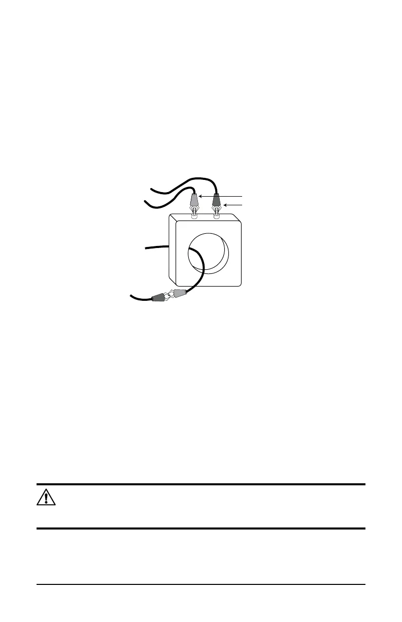
Current Transformer (CT) ratio testing is performed by connecting the H
cablesettotheXwinding,andbyshortingtheXcablesetthroughthe
CTaperture,asdepictedbelow.Thiscreatesastep-downconguration
inwhichtheXwindingservesastheprimarycircuit,andtheXcableset
serves as a one-turn secondary winding.
CURRENT TRANSFORMER
X RED
X BLACK
H RED
H BLACK
X2 X1
4.4.2 CT Testing
1.
When the instrument is set for CT testing, the DTR
®
will display the CT
TestModeSelectedmessageaftertheinitialpower-upsequence.This
message indicates that the DTR
®
is now ready to execute a test.
2. Press the TEST button once to begin the test cycle.
3. The next message displayed is *Ratio Testing [TEST] to Cancel. The
asterisk ( * ) will blink as testing proceeds. Testing may be cancelled at
this time by pressing the TEST button once. If the test continues, Ratio
and Excitation current will be displayed.
4. Once test results are recorded, press the TEST button to reset for the
next test.
NOTE: There are certain low mass, low ratio CT’s where the DTR
®
may not be able to provide the correct ratio. The error message will
be“HighExcitationCurrent.”
As in VT/PT Test Mode, this routine may be repeated as many times as
needed without powering down the unit. The CT Test Mode remains active
until the unit is powered down.