Other characteristics and features.
- Internal warning signal indicating a failure in one of the power supplies. If a failure occurs, the
“ALARM” LED on the BC2240 controller board will light up.
- Power feed circuit designed to support hot-swapping operations.
- Digital adjustment of analog gain (±12 dB) in the 4 inputs.
- Digital adjustment of digital gain (-40/+24 dB) in the 4 inputs.
Programming jumpers.
This board has a series of internal programming jumpers (PJ). By default, this board is
configured to work with high impedance headphones (higher than 150Ω). If you use low
impedance headphones (below 150Ω), you will need to pull the board out and change the J1,
J2, J3 and J4 jumpers on the board marked "472-001-311" to position 2-3.
Firmware modules.
At the firmware level, this board is made up of the following modules:
- PIC microcontroller: manages board communications and start-up.
- FPGA programmable device: manages the converters and the TDM bus.
The firmware versions can be brought up to date by using the “BC2000D Firmware Upgrade”
software application.
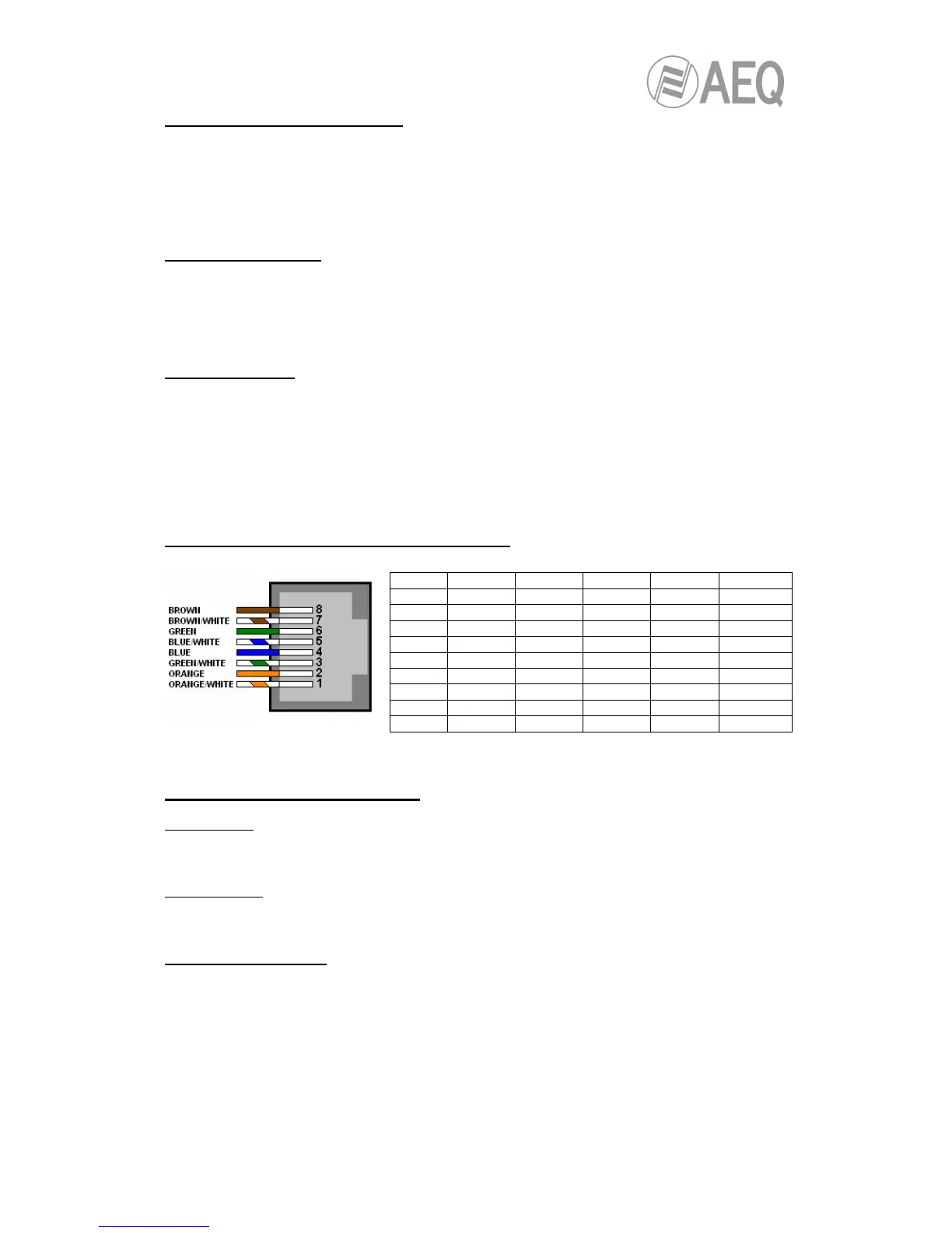
Signal layout in the RJ45 connectors of the board.
NOTE: Pin layout corresponds to T568B standard.
BC2203MHL technical specifications.
Analog inputs:
- 24-bit, 48 kHz A/D converters.
- PHANTOM power supply voltage: +48 V (software configurable).
Analog outputs:
- 24-bit, 48 kHz D/A converters.
- Capacity to feed high and low impedance headphones.
General characteristics.
- Approximate consumption: 7.5 watts.
- Approximate dimensions:
Front: 34 x 172 mm.
Depth: 255 mm.
- Approximate weight: 560 grams.
Characteristics are subject to change without notice.
Pin '1' Input 1