7.2. ARENA D10 channel expansion module.
Composition of the supply.
• The module itself.
• One 2-meter power supply cable.
• Flexible shielded RJ45/RJ45 cable for ARENA D10, 2 meters long.
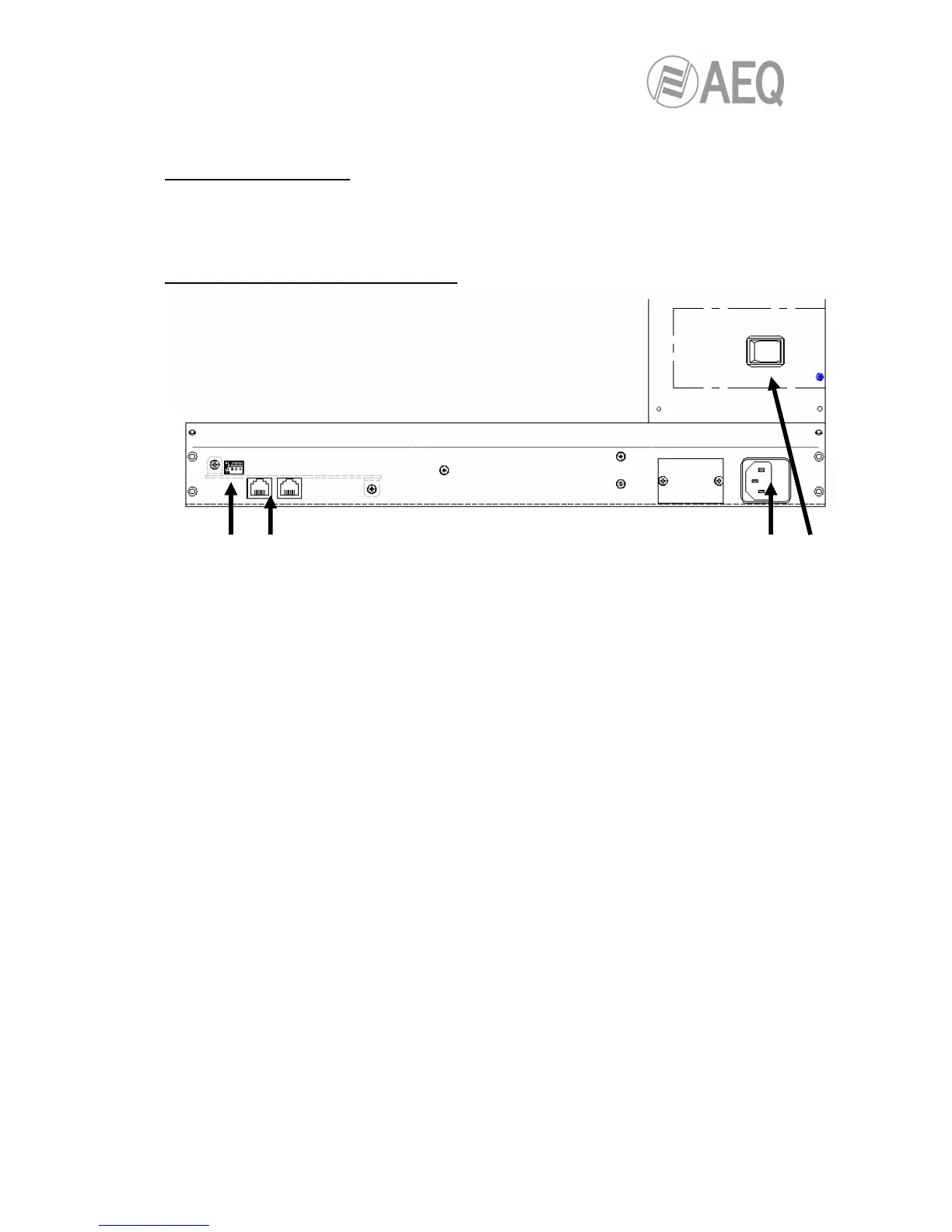
Connection and other rear panel elements.
• 1. Power switch
• 2. Power supply connector and fuse.
• 3. Pair of RJ45 input and output connectors, where output follows the RS 422 control
from the main ARENA DM module and toward others, for ARENA D10 channel
expansion modules. Pin-to-pin connection (the cable furnished with each module can
be used), since the pin layout is inverted in the equipment. Pin layout, from right to left,
with the tongue facing up:
3. TX +.
4. RX +.
5. RX -.
6. TX -.
7. S clk +: V+ phase of the synchronizing signal.
8. S clk -: V- phase of the synchronizing signal.
• 4. Dip-Switch module. These switches are used to assign a different address to each
ARENA D10 module that hangs from a ARENA DM, to prevent communications from
colliding. Make sure, therefore, that in each ARENA D10 the position of the set of dip-
switches is different from all the rest of the dip-switches.