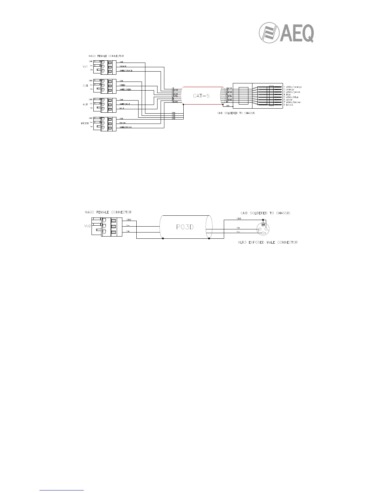
Cable is furnished to connect to BC 2000 CAB W module:
IMPORTANT NOTE: GND is soldered to chassis in RJ45 connector.
• 5. AES/EBU digital audio connector by XLR, to receive the input from VU meter 2.
1. GROUND.
2. AES VU2 In +: AES/EBU audio input for VU meter 2.
3. AES VU2 In -: AES/EBU audio input for VU meter 2.
The cable used to connect to BC 2000 CAB W module is as follows:
IMPORTANT NOTE: Pin 1 (GND) is soldered to chassis in XLR connector.
• 6. Pair of RS 422 control output RJ45 connectors for ARENA D10 channel expansion
modules: 2 connectors. If you need to connect more (up to 7), each connector has a
follower output that can be connected to the next one. Pin layout, from right to left, with
the tongue facing up:
3. RX +.
4. TX +.
5. TX -.
6. RX -.
7. S clk +: V+ phase of the synchronizing signal.
8. S clk -: V- phase of the synchronizing signal.
Normal Ethernet cable is used (according to T568B standard).
• 7. RS 232: serial Port: Connection via serial port for future applications.