Other characteristics and features.
- Internal warning signal indicating a failure in one of the power supplies. If a failure occurs, the
“ALARM” LED on the BC2240 controller board will light up.
- Power feed circuit designed to support hot-swapping operations.
- Digital adjustment of digital gain (±12 dB) in the 4 outputs.
- Possibility of converting the module so that it can use SPDIF signals by manipulating the
internal programming jumpers.
Programming jumpers.
This board is equipped with a series of internal programming jumpers (PJ) that allow you to
change the format of the digital signal to be used between AES3 and SPDIF. You can
independently change the format of each one of the four audio channels (circuit 0, 1, 2 and 3)
by changing the following PJs:
CN17, CN23, CN25, CN55
AES3 / SPDIF digital audio selectors for output circuit 0.
1-2: AES3 Digital Audio.
2-3: SPDIF Digital Audio.
CN30, CN39, CN40, CN56
AES3 / SPDIF digital audio selectors for output circuit 1.
1-2: AES3 Digital Audio.
2-3: SPDIF Digital Audio.
CN20, CN27, CN29, CN57
AES3 / SPDIF digital audio selectors for output circuit 2.
1-2: AES3 Digital Audio.
2-3: SPDIF Digital Audio.
CN34, CN42, CN43, CN58
AES3 / SPDIF digital audio selectors for output circuit 3.
1-2: AES3 Digital Audio.
2-3: SPDIF Digital Audio.
The default position of these PJs is 1-2; that is, they are configured to work with digital audio in
AES/EBU format.
Firmware modules.
At the firmware level, this board is made up of the following modules:
- PIC microcontroller: manages board communications and start-up.
- FPGA programmable device: manages SRCs and the TDM bus.
The firmware versions can be brought up to date by using the ”BC2000D Firmware Upgrade”
software application.
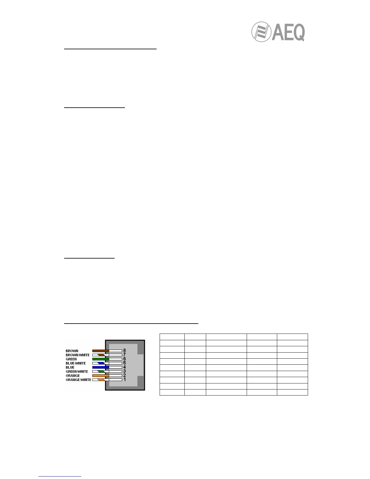
Signal layout in the RJ45 connectors of the board.
NOTE: Pin layout corresponds to T568B standard.
Pin
-
'2' Outputs '3' GPI '4' GPO
8 - OUT 2 (1R) N GND GPI2 GND GPO2