Other characteristics and features.
- Internal warning signal indicating a failure in one of the power supplies. If a failure occurs, the
“ALARM” LED on the BC2240 controller board will light up.
- Power feed circuit designed to support hot-swapping operations.
Programming jumpers.
This board has a series of internal programming jumpers (PJ). However, these jumpers are
configured at the factory and, in normal operation, do not need to be changed.
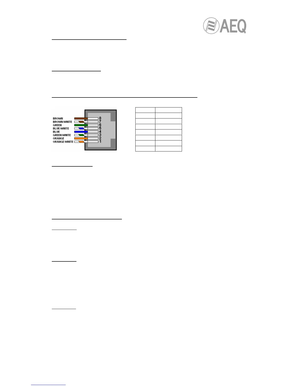
Signal layout in the RJ48 connectors of the board (standard mode).
Firmware modules.
At the firmware level, this board is made up of the following modules:
- PIC microcontroller: manages board communications and start-up.
- FPGA programmable device: manages the TDM bus.
The firmware versions can be brought up to date by using the ”BC2000D Firmware Upgrade”
software application.
BC2215 technical specifications.
E1 Interface:
- 2048 Kbps: One 64 Kbps slot for synchronization y 1984 Kbps (31 slots) available.
- Selection of AMI or HDB3 line code. HDB3 compatible with ITU standard G703.
- Standard framework compatible with ITU G704.
- Line impedance: 120/75Ω software configurable.
T1 Interface:
- 1554 Kbps (1 bit per frame is used for frame and multiframe synchronization, alarm
monitoring, etc.). 24 slots of 64 Kbps available.
- Selection of AMI or B8ZS line code. B8ZS compatible with ITU standard G703.
- Standard framework compatible with D4-ATT PUB 4801.
- Selection of superframe in 193S (12 frames per multiframe) or 193E (24 frames per
multiframe) framing format.
- Line impedance: 100Ω.
J1 Interface:
- Characteristics similar to those of T1 interface with CRC6 management and yellow alarm
according to the Japanese standard.
8 GND
7 GND
6
5 Tx+
4 Tx-
3
2 Rx+
1 Rx-
 Loading...