Firmware modules.
At the firmware level, this board is made up of the following modules:
- PIC microcontroller: manages board communications and start-up.
- FPGA programmable device: manages the alarms and the TDM bus.
The firmware versions can be brought up to date by using the ”BC2000D Firmware Upgrade”
software application.
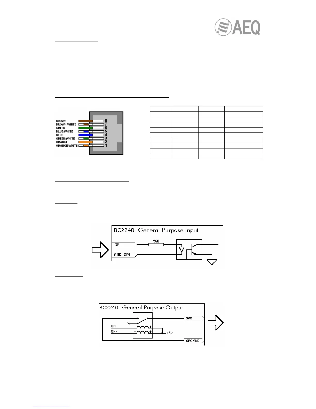
Signal layout in the RJ45 connectors of the board.
NOTE: Pin layout corresponds to T568B standard.
BC2240 technical specifications.
External synchronism: AES3 and TTL.
GPI inputs:
- Inputs protected by optocoupler (4N35).
- Maximum input current: 60 mA.
- A voltage ranging between 5 V and 30 V will be applied.
GPO outputs:
- By bistable relay (contact closing).
- Maximum current: 1 A @ 30 V DC, 0.5 A @ 125 V AC.
- Maximum voltage: 110 V DC or 125 V AC.
- Maximum power: 30 W, 62.5 VA.
Pin 'GPI' 'GPO' 'EXT. SYNC.'
8 GPIGND GPOGND AES SYNC IN-
7 GPI7 GPO7 AES SYNC IN+
6 GPI6 GPO6 AES SYNC OUT-
5 GPI5 GPO5 AES SYNC OUT+