AM Series Boiler Heat Exchanger Maintenance & Replacement
Technical Instruction Document
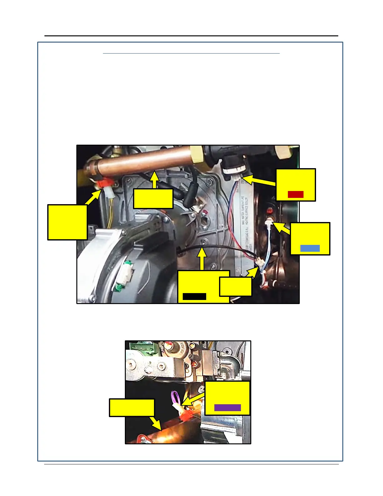
Connecting Cables and Wiring Connections
2. Route the Yellow wire up behind the gas valve and connect to the return sensor.
3. On the right side of the blower assembly, the cable with the red wire is connected to the
flow meter.
4. Insert the connector on the black flapper valve wire (coming from the blower assembly)
into the connector on the harness, as shown in Figure-5-3. This connector is tied with the
other cables on the right side (per routing in Step 1) but can be identified by its shorter
lead out from the cable tie.
5. Connect harness with blue wire to the flue sensor (blue connector) on the right side of
the heat exchanger. See Figure 5-3.
Figure 5-3: Return Sensor, Flow Meter, Flapper Valve Connections
6. On the left side of the blower assembly, the purple wire is connected the supply sensor,
which is located below the gas valve and on the supply piping. See Figure 5-4.
Figure 5-4: Supply Sensor Connection
FLAPPER
VALVE WIRE
STEP 2:
RETURN
SENSOR
(YELLOW)
SUPPLY
SENSOR
(PURPLE)
FLOW
METER
PIPING
FLUE
SENSOR
TID-0132_99 AERCO International, Inc. • 100 Oritani Dr. • Blauvelt, NY 10913 Page 30 of 36
Ph.: 800-526-0288 01/18/2015
 Loading...