Benchmark 6000 Boiler Installation, Operation & Maintenance Manual
CHAPTER 7 – MAINTENANCE
Page 100 of 210 AERCO International, Inc. • 100 Oritani Dr. • Blauvelt, NY 10913 OMM-0086_0D
03/20/14 Ph.: 800-526-0288 GF-133
Burner Assembly Inspection and Maintenance Procedures – Continued
NOTE
The Blower assembly is heavy, weighing approximately 200 lbs
15. Lower the Blower/Air/Fuel Valve assembly down approximately 16” until it is clear of the
Burner Flange.
16. Remove the Burner by pulling straight out.
17. Gently slide the Burner out of the boiler using care to avoid tearing the mesh burner fabric,
or cock the Burner to one side or the other.
18. Remove and replace the two (2) Burner Gaskets (see Figure 7-5).
19. To reassemble, begin with the Burner assembly and reinstall all the components in the
reverse order that they were removed. The Burner may have a nut installed at the base
position to keep the Burner level while installing the Blower (Figure 7-5).
20. Ensure that the Pilot Burner and Pilot Flame Detectors cutouts in the Blower Flange are
properly aligned with the Burner Plate.
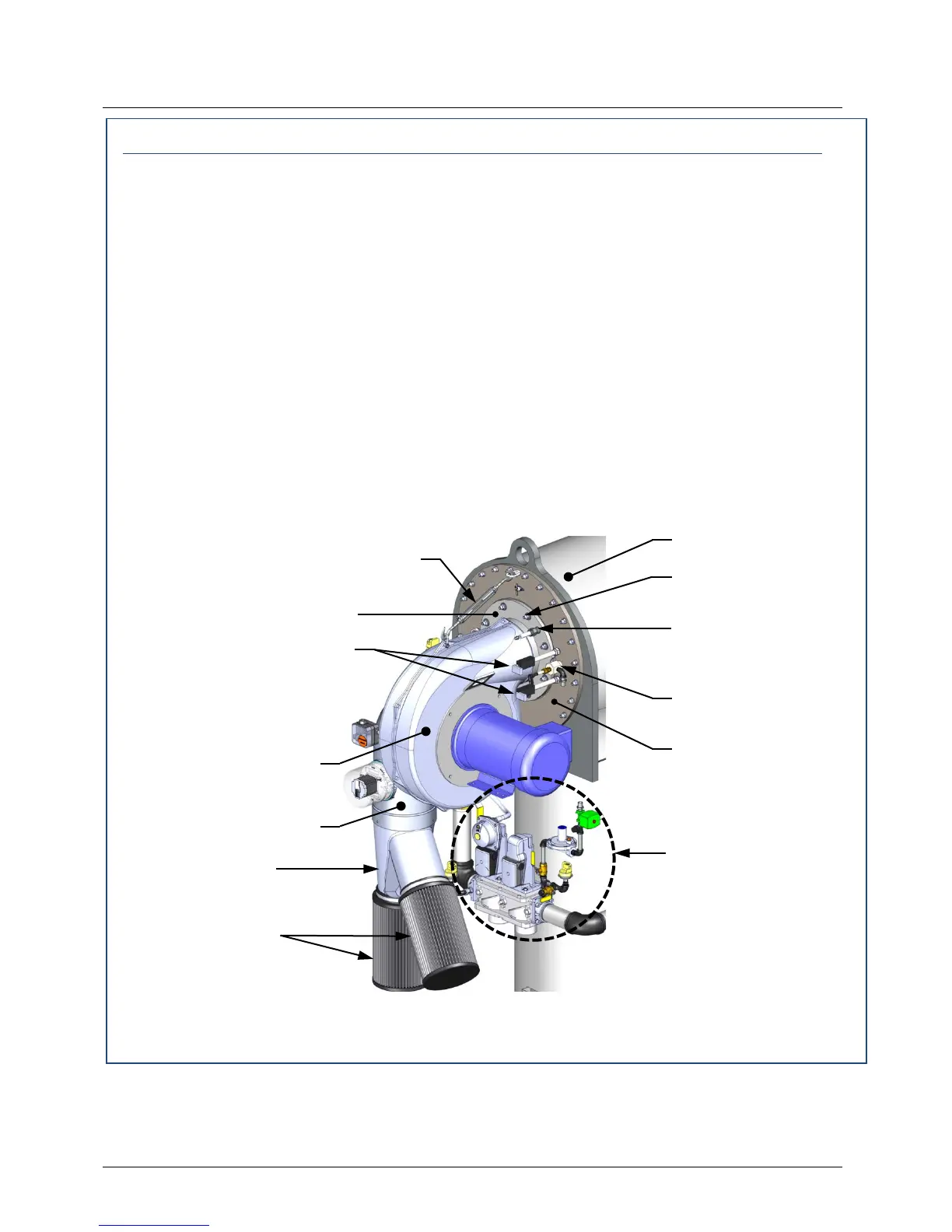
Figure 7-4a: Burner Assembly Mounting Details
WASHERS (8)