Benchmark 6000 Boiler Installation, Operation & Maintenance Manual
CHAPTER 2 – INSTALLATION
Page 28 of 210 AERCO International, Inc. • 100 Oritani Dr. • Blauvelt, NY 10913 OMM-0086_0D
03/20/14 Ph.: 800-526-0288 GF-133
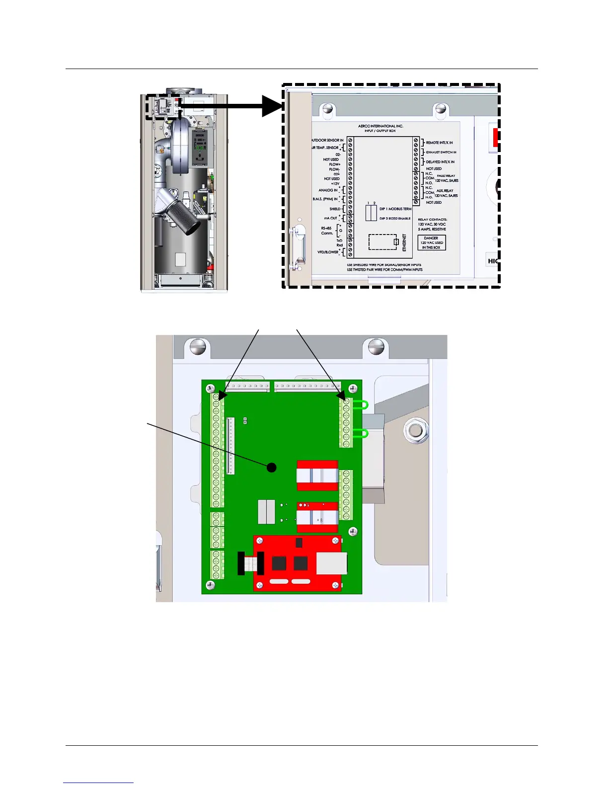
Figure 2-12a: Input/Output (I/O) Box Location
Figure 2-12b: Input/Output (I/O) Box Interior
NOTE
Use Figure 2-13 to determine the functions of the I/O PCB
connections. Do not use the silkscreened labels on the PCB itself,
as these may not match the function names. There is a diagram of
the connection functions on the cover of the I/O Box as well.
I/O PCB
BOARD
TERMINAL STRIPS
located in the
unit’s upper-left
corner.